 ALLPCB


RRC Connection Establishment
In mobile communication, the UE and the RAN must first complete RRC connection establishment. In 5G there are two mechanisms for RRC connection establishment.
RRC in 5G (NR)
Scenario 1: After the UE establishes an RRC connection with the gNB, the gNB connects to the 5G core network. This is a typical 5G deployment.
Scenario 2: In Multi-RAT dual connectivity, the UE first establishes an RRC connection on 4G (LTE), then establishes a connection with the gNB. This is common in early 5G deployments using the NSA architecture (no 5G core deployed). In this case, connection control (air-interface RRC signaling) is handled by the 4G eNB connected to the 4G EPC; the 5G gNB only supplements the UE user plane. RRC signaling messages between the UE and gNB can be exchanged directly using SRB3 or indirectly via the eNB.
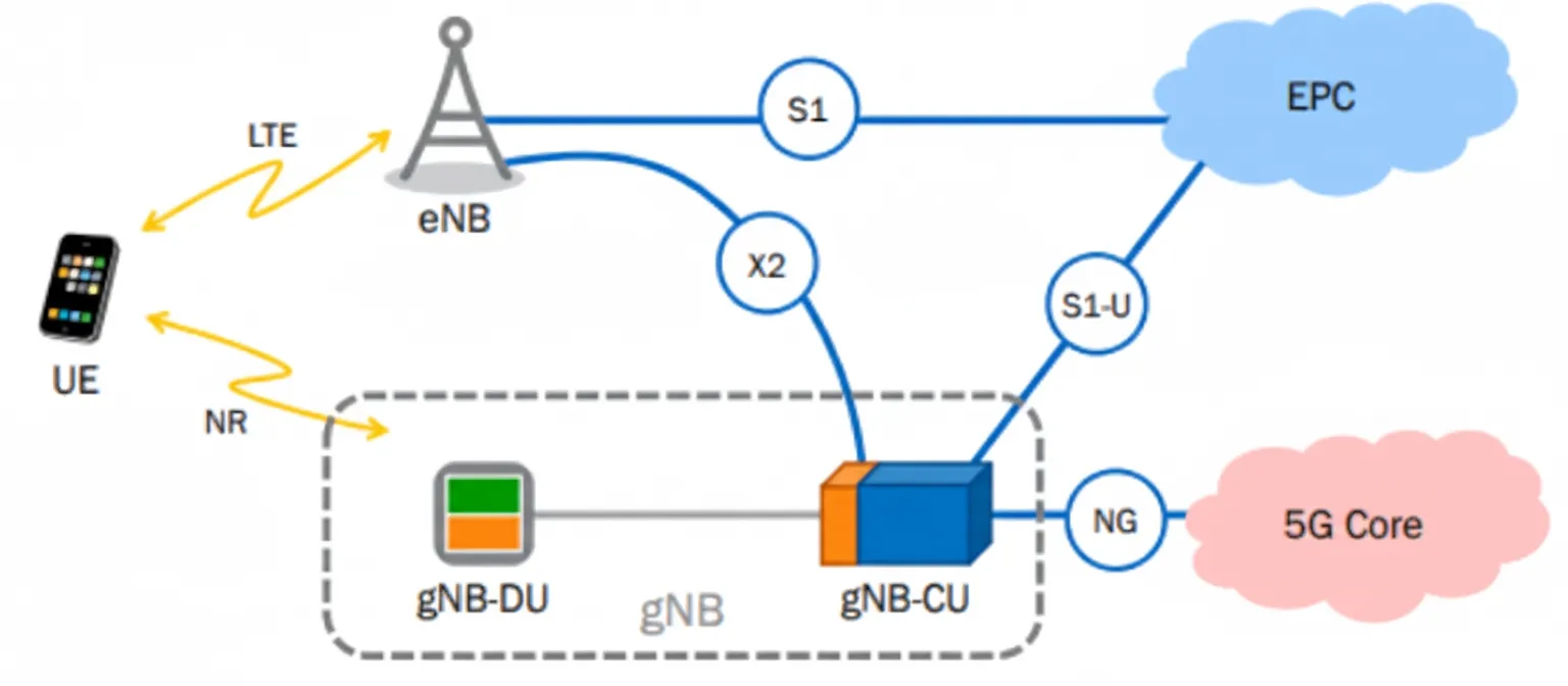
Figure 1. Basic 5G (NR) network architecture and interfaces
RRC Connection Establishment: Mechanism One
In 5G SA deployments the gNB is split into gNB-CU and gNB-DU with an F1 interface between them. The F1 interface and F1AP messages are key to the RRC connection establishment process.
F1 Setup
To make the F1 interface operational and start exchanging messages or user plane traffic, the F1 interface must be configured. The gNB-DU sends an F1 setup request and receives an F1 setup response from the gNB-CU. During this exchange any existing UE-related context is reset if applicable.
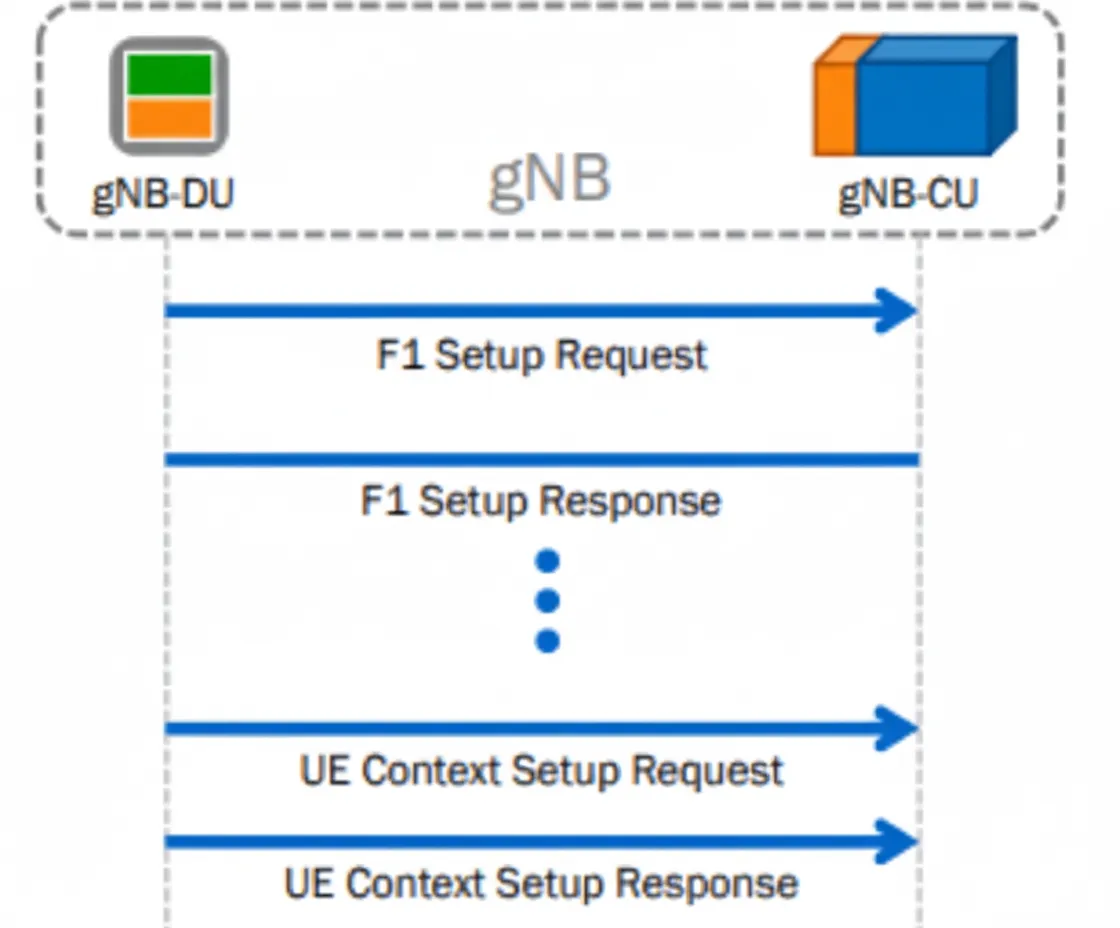
Figure 2. RRC connection flow one in 5G (NR) network
UE Context Setup
A new UE context must be established for each UE supported by the gNB. The context includes information about bearers such as SRBs and DRBs. The gNB-CU initiates the request and provides the PCell ID and/or SCell ID and the details of the SRBs or DRBs to be established.
Dual Connectivity
For dual connectivity scenarios, these messages are exchanged between the eNB and the ng-gNB over the X2 interface.
RRC Connection Establishment: Mechanism Two
This flow describes RRC connection establishment in the 5G SA architecture. Related 3GPP specifications are still being finalized, so call flows and message names may change. In NSA deployments, RRC connections are set up according to the 4G (LTE) specification TS 36.331.
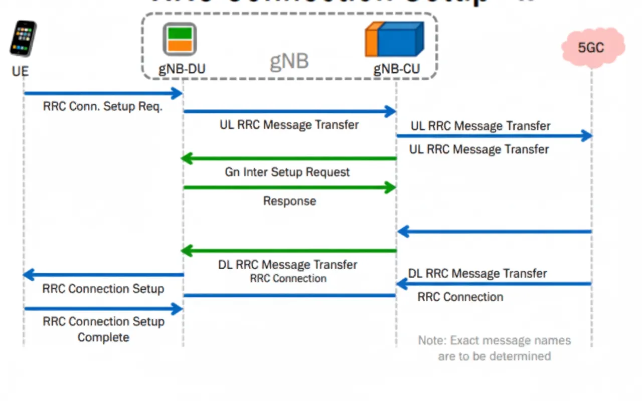
Figure 3. RRC connection flow two in 5G (NR) network
Sequence summary:
- The UE sends an RRC connection request to the gNB. Because the gNB is split into gNB-DU and gNB-CU, the message first arrives at the gNB-DU.
- The gNB-DU places the RRC connection request into an UL RRC message transfer and forwards it to the gNB-CU.
- The gNB-CU sends a NAS message to the AMF to establish or activate the UE context in the 5G core.
- The AMF responds using a NAS message.
- The gNB-CU responds via DL RRC message transfer, which contains the RRC connection setup to be returned to the UE.
- The gNB-DU sends the RRC connection setup to the UE.
- The UE replies with RRC connection setup complete.


