 ALLPCB


Introduction
Wearable devices for vital-sign monitoring (VSM) are enabling continuous measurement of physiological signals and activity. Measuring body impedance provides relevant information for several key parameters.
To be effective, wearable devices must be compact, low-cost, and energy-efficient. Measuring bioimpedance also introduces challenges related to the use of dry electrodes and safety requirements. This article outlines solutions to those challenges.
Electrode Half-Cell Potential
Electrodes are electrical sensors that provide contact between an electronic circuit and a nonmetallic object such as human skin. This interaction produces a voltage known as the half-cell potential, which reduces the dynamic range available to the ADC. The half-cell potential varies with electrode material, as shown in Table 1.
When no current flows through the electrode, the half-cell potential can be observed. When DC current flows, the measured voltage increases. This overpotential impedes current flow, polarizes the electrode, and degrades performance, especially during movement. For most biomedical measurements, nonpolarizing (wet) electrodes perform better than polarizing (dry) electrodes. Portable consumer devices commonly use dry electrodes because they are low cost and reusable.
Electrode-to-Skin Impedance
Figure 1 shows the equivalent circuit of an electrode. Rd and Cd represent the impedance and polarization at the electrode-skin interface. Rs is the series resistance associated with the electrode material type, and Ehc is the half-cell potential.
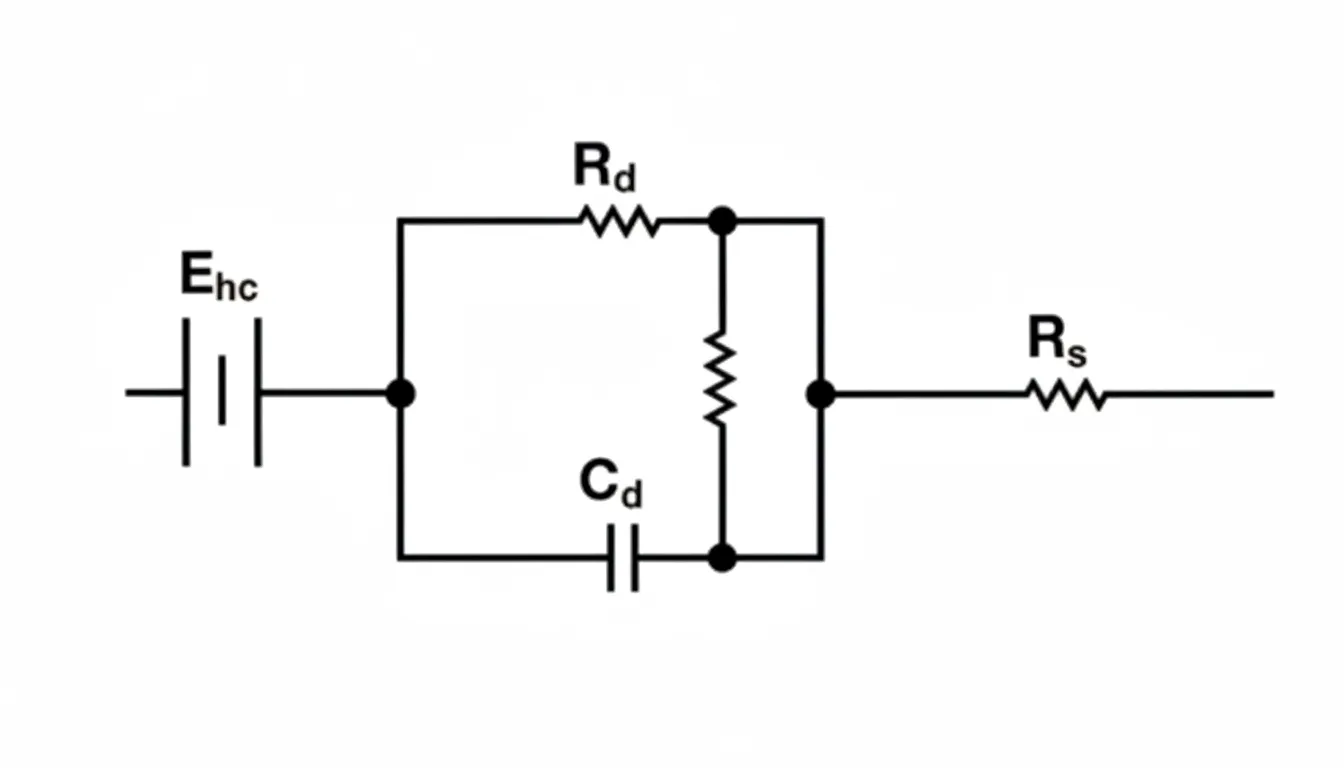
Figure 1. Equivalent circuit model of a bioelectrode.
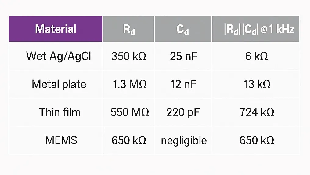
Because high impedances are involved, the electrode-to-skin impedance is an important parameter when designing the analog front end. At low frequencies, the series combination of Rs and Rd dominates. At higher frequencies, capacitive effects reduce the impedance toward Rd. Table 2 lists typical values for Rd, Cd, and the impedance at 1 kHz.
Safety Standards
IEC 60601 is a set of technical standards published by the International Electrotechnical Commission that address the safety and performance of medical electrical equipment. It specifies a maximum DC leakage current through the body of 10 μA under normal conditions and 50 μA under the single worst-case fault condition. The maximum allowable AC leakage current depends on the excitation frequency. If the frequency (f) is less than or equal to 1 kHz, the maximum allowed current is 10 μA rms. If the frequency is greater than 1 kHz, the maximum allowed current is
These patient-current limits are important circuit-design parameters.
Circuit Design Solutions
Impedance measurement requires a voltage/current source and a current/voltage meter, so DACs and ADCs are commonly used. Precise voltage references and voltage/current control loops are critical for computing the real and imaginary parts of impedance, and a microcontroller is typically required for data processing. Wearables are usually powered by a single-cell battery. Integrating as many functions as possible into a single package is advantageous. The ADuCM350 is an ultra-low-power integrated mixed-signal instrumentation chip that includes a Cortex-M3 processor and hardware accelerators capable of executing single-frequency discrete Fourier transforms (DFT), and can be used in wearable devices.
To meet IEC 60601 requirements, the ADuCM350 can be used with the AD8226 instrumentation amplifier to perform four-wire measurements for high-precision results, as shown in Figure 2. Capacitors CSIO1 and CSIO2 block DC current between the electrodes and the user, eliminating polarization effects. The AC excitation from the ADuCM350 is applied to the body.
Capacitors CSIO3 and CSIO4 block the DC offset from the ADC, addressing the half-cell potential and preserving maximum dynamic range. CSIO1, CSIO2, CSIO3, and CSIO4 provide electrical isolation from the user, ensuring zero DC current under normal operation and under a first-fault condition, as well as zero AC current under a first-fault condition. Finally, resistor RLIMIT ensures the AC current remains below the limit during normal operation. RACCESS indicates the contact between skin and electrode.
The ADuCM350 measures the current from the transimpedance amplifier (TIA) and the output voltage of the AD8226 to compute the unknown body impedance. RCM1 and RCM2 must be as large as possible to ensure most current flows through the unknown body impedance and the TIA. A suggested value is 10 MΩ.
Design Limitations
This design has limitations when the electrode-to-skin impedance at the excitation frequency approaches 10 MΩ. The electrode-to-skin impedance must be much smaller than RCM1 and RCM2 (10 MΩ); otherwise VINAMP+ will not equal node A and VINAMP– will not equal node B, and measurement accuracy will degrade. At excitation frequencies above 1 kHz, electrode-to-skin impedance is typically well below 1 MΩ.
Validation
To demonstrate accuracy, the system was tested with different unknown impedances and compared with measurements from an Agilent 4294A impedance analyzer. In all tests the amplitude error was less than ±1%. At 500 Hz and 5 kHz the absolute phase error was less than 1°. At 50 kHz a 9° phase bias was observed; this bias can be corrected in software.
Conclusion
When designing battery-powered wearable devices that measure impedance, low power consumption, high signal-to-noise ratio, electrode polarization, and IEC 60601 safety requirements must be considered.


