 ALLPCB


Introduction
Printed Circuit Boards, or PCBs, form the backbone of modern electronics, connecting and supporting various components to create functional devices. For electronic hobbyists, understanding and identifying common PCB components for beginners is a crucial first step in building, troubleshooting, or repairing circuits. Whether you are working on a simple LED project or a complex microcontroller setup, recognizing components like resistors, capacitors, and diodes on a circuit board can save time and prevent errors. This guide aims to simplify the process of identifying resistors on a PCB, understanding capacitor types on PCBs, and recognizing diodes on a circuit board. With a focus on basic electronic components, this article provides clear explanations and practical tips to help hobbyists gain confidence in navigating the intricate world of PCBs.
Why Identifying PCB Components Matters
Identifying components on a PCB is fundamental for anyone venturing into electronics as a hobby. Each component plays a specific role in a circuit, and misidentification can lead to incorrect connections, circuit failure, or even safety hazards. For beginners, learning to spot resistors, capacitors, and diodes ensures accurate assembly and effective troubleshooting. This skill also aids in reading schematics and understanding how a circuit functions as a whole. Beyond functionality, recognizing these parts helps in sourcing replacements or upgrading designs. As hobbyists progress, familiarity with basic electronic components guides them toward more complex projects, fostering a deeper appreciation for circuit design and innovation.
Common PCB Components for Beginners
To build a strong foundation, hobbyists should focus on the most frequently used components found on PCBs. Below is a detailed breakdown of essential parts, their roles, and how to identify them visually and through markings.
Resistors
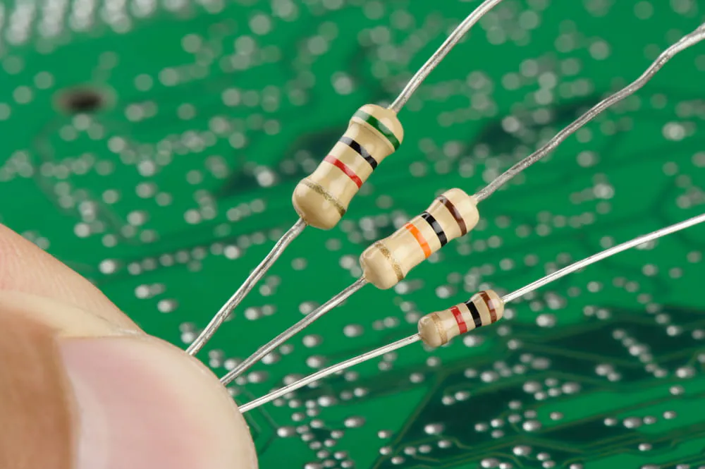
Resistors limit current flow and protect other components by controlling voltage levels in a circuit. Identifying resistors on a PCB is often straightforward due to their distinct appearance and markings. They typically appear as small cylindrical or rectangular parts with colored bands or numerical codes. Through-hole resistors, common in beginner projects, have long leads for easy soldering, while surface-mount resistors are smaller and flat, often labeled with a three or four-digit code.
To read resistor values, look for the color bands on through-hole types, which follow a standardized code to indicate resistance and tolerance. Surface-mount resistors use numbers, where the last digit often represents a multiplier. Familiarity with these markings is key for accurate identification.
Capacitors
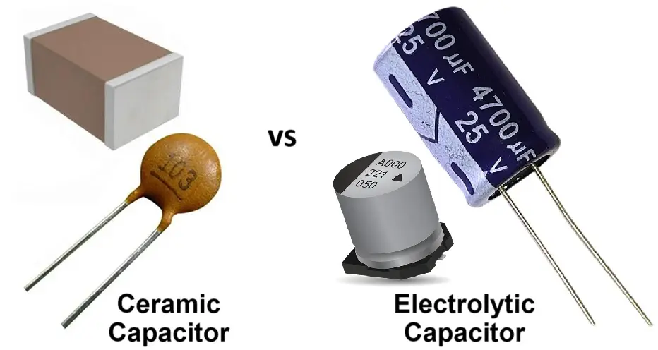
Capacitors store and release electrical energy, smoothing out voltage fluctuations or filtering signals. Understanding capacitor types on PCBs is essential, as they come in various forms, each suited to specific applications. Electrolytic capacitors, often used for power supply filtering, are cylindrical with polarity markings, usually a stripe indicating the negative lead. Ceramic capacitors, smaller and non-polarized, appear as tiny discs or chips with no clear orientation markings.
For identification, check the labeling on larger capacitors, which may show capacitance in microfarads or picofarads, along with voltage ratings. Smaller ones might have a three-digit code, similar to resistors, indicating their value. Polarity awareness is critical for electrolytic types to avoid damage during installation.
Related Reading: Beginner's Guide to Battery Charger PCB Components: What You Need to Know
Diodes
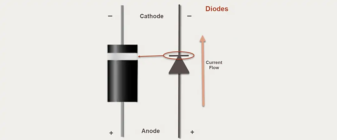
Diodes allow current to flow in one direction only, protecting circuits or converting alternating current to direct current. Recognizing diodes on a circuit board often involves spotting their unique shape and markings. Through-hole diodes are small cylindrical components with a band on one end indicating the cathode, or negative side. Surface-mount diodes are tiny and rectangular, with a line or symbol denoting polarity.
Light-emitting diodes, or LEDs, a common subtype, emit light when powered and also follow polarity rules. Always align the cathode and anode correctly to ensure proper function. Visual inspection of the band or symbol is the simplest way to identify and orient diodes in a circuit.
Other Basic Components
Beyond resistors, capacitors, and diodes, hobbyists should recognize a few additional parts. Transistors, acting as switches or amplifiers, come in various packages like TO-92 for through-hole or small flat shapes for surface-mount. Integrated circuits, or ICs, are multi-functional chips often seen as black rectangular components with multiple pins, labeled with part numbers. Inductors, used for filtering or energy storage, resemble small coils or toroidal shapes. Familiarity with these basic electronic components guides beginners in tackling diverse projects.
Technical Principles Behind Component Identification
Understanding the physical and functional characteristics of PCB components aids in accurate identification. Resistors, for instance, are designed to resist current, and their value markings follow standards set by organizations like the International Electrotechnical Commission, or IEC, ensuring consistency across manufacturers. Capacitors vary in material and construction, affecting their appearance and application, with polarity being a critical factor for certain types as per guidelines in standards like IPC-A-600K.
Diodes rely on semiconductor properties to control current direction, and their polarity markings are universally standardized to prevent reverse installation. Visual cues, combined with schematic symbols, provide a reliable method for recognition. Hobbyists can refer to documentation like IPC-6012E for insights into component placement and identification during PCB assembly, ensuring alignment with industry practices.
Related Reading: 15 Key Diode Parameters
Practical Tips for Identifying Components
For hobbyists, hands-on practice is the best way to master component identification. Start by studying the PCB layout and silkscreen markings, which often include reference designators like R for resistors, C for capacitors, and D for diodes, followed by a number. Use a magnifying glass to inspect small surface-mount parts for codes or symbols indicating value or polarity.
Invest in a multimeter to test components when markings are unclear. Set it to resistance mode to confirm resistor values or diode mode to check polarity and functionality. Keep a reference chart for resistor color codes and capacitor markings handy for quick lookups. When working on a new board, compare it against the schematic or bill of materials if available to verify component placement.
For safety, always discharge capacitors before handling, especially larger electrolytic types, to avoid electric shock. Practice on scrap or practice boards to build confidence without risking damage to functional projects. Over time, visual recognition becomes second nature, speeding up assembly and repair tasks.
Troubleshooting Common Identification Challenges
Beginners often face challenges in distinguishing similar-looking components or reading faded markings. Surface-mount parts, due to their small size, can be particularly tricky. If codes are unreadable, rely on the circuit context; for example, components near power inputs are likely capacitors or diodes for filtering or protection.
Misidentifying polarity in diodes or capacitors can lead to circuit failure. Always double-check markings before soldering, and if unsure, test with a multimeter. Some PCBs lack silkscreen labels, so tracing the circuit path to understand component roles can provide clues. If a component’s function remains unclear, refer to widely accepted design practices in standards like IPC-A-600K for guidance on typical placements.
Conclusion
Mastering the identification of essential PCB components opens the door to successful electronics projects for hobbyists. By focusing on common PCB components for beginners, such as resistors, capacitors, and diodes, individuals can build a solid foundation for circuit assembly and troubleshooting. Practical skills like reading markings, understanding polarity, and using tools like multimeters enhance accuracy in recognizing diodes on a circuit board and other parts. With consistent practice and adherence to industry standards, hobbyists can confidently navigate the complexities of PCBs, turning ideas into functional designs. This basic electronic components guide serves as a starting point for lifelong learning in electronics.
FAQs
Q1: What are the most common PCB components for beginners to learn first?
A1: As a beginner, start with resistors, capacitors, and diodes. These are fundamental to most circuits and frequently used in hobbyist projects. Resistors control current, capacitors store energy, and diodes direct current flow. Learning to identify their shapes, markings, and polarity ensures a strong foundation for building and troubleshooting simple circuits.
Q2: How can I practice identifying resistors on a PCB without a schematic?
A2: Use visual cues like color bands on through-hole resistors or numerical codes on surface-mount types to determine their values. A multimeter in resistance mode can confirm readings. Inspect the PCB silkscreen for labels like R1 or R2. Practice on old or scrap boards to build familiarity with resistor appearances and placements.
Q3: What should I know about understanding capacitor types on PCBs?
A3: Capacitors vary in type, such as electrolytic for power filtering and ceramic for signal applications. Electrolytic ones are polarized, marked with a negative stripe, while ceramic types are not. Check labels for capacitance and voltage ratings. Incorrect orientation of polarized capacitors can damage circuits, so always verify markings before installation.
Q4: What is the easiest way for recognizing diodes on a circuit board?
A4: Look for a band or line on one end of the diode, indicating the cathode or negative side. Through-hole diodes are cylindrical, while surface-mount ones are small and flat. LEDs, a diode type, often have a flattened edge for polarity. Use a multimeter in diode mode to confirm direction if markings are unclear.
References
IPC-6012E - Qualification and Performance Specification for Rigid Printed Boards. IPC, 2020.
IPC-A-600K - Acceptability of Printed Boards. IPC, 2020.


