 ALLPCB


If you're looking to optimize laser drilling parameters for PCB materials like FR-4, Rogers, ceramic, PTFE, or metal core PCBs, you've come to the right place. Laser drilling is a precise and efficient method for creating vias and holes in printed circuit boards (PCBs), but the parameters must be tailored to each material to achieve the best results. In this comprehensive guide, we'll dive into the specific laser drilling parameters for each of these materials, ensuring high-quality outcomes with minimal damage or defects. Whether you're an engineer or a manufacturer, this blog will provide actionable insights to enhance your PCB production process.
Introduction to Laser Drilling in PCB Manufacturing
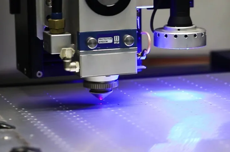
Laser drilling has become a cornerstone in modern PCB manufacturing due to its ability to create small, precise holes (vias) with high accuracy. Unlike traditional mechanical drilling, laser drilling uses a focused beam of light to remove material, making it ideal for high-density interconnects and microvias. However, different PCB materials have unique properties—such as thermal conductivity, dielectric constants, and hardness—that require specific laser settings to avoid issues like charring, cracking, or poor hole quality.
In this blog, we'll explore how to fine-tune laser drilling parameters for popular PCB materials, including FR-4, Rogers, ceramic, PTFE, and metal core PCBs. By understanding the characteristics of each material and adjusting settings like laser power, pulse duration, and repetition rate, you can achieve optimal results in your manufacturing process.
Why Laser Drilling Parameters Matter
Before diving into specific materials, it's important to understand why laser drilling parameters are critical. Parameters such as laser wavelength, power, pulse duration, and focus spot size directly impact the quality of the holes drilled. Incorrect settings can lead to problems like:
- Excessive heat damage or burning of the material.
- Incomplete material removal, resulting in poor via conductivity.
- Cracking or delamination in brittle or multi-layer materials.
- Inconsistent hole sizes, affecting the reliability of the PCB.
Optimizing these parameters ensures clean, precise holes, reduces production defects, and enhances the overall performance of the PCB. Now, let’s break down the best practices for each material type.
Laser Drilling Parameters for FR-4
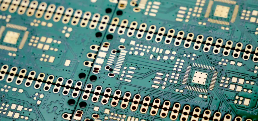
FR-4 is one of the most common PCB materials, made from a woven fiberglass cloth with an epoxy resin binder. It’s cost-effective and widely used in consumer electronics, but its composite nature makes laser drilling challenging due to the differing thermal properties of glass and resin.
Key Parameters for FR-4:
- Laser Type: CO2 lasers (wavelength around 10.6 μm) are often used for FR-4 as they effectively ablate the epoxy resin. UV lasers (355 nm) are also suitable for finer vias.
- Power: Moderate power levels (10-20 W for CO2 lasers) prevent excessive heat buildup, which can cause charring of the resin.
- Pulse Duration: Short pulses (microseconds to nanoseconds) minimize thermal damage to the surrounding material.
- Repetition Rate: A rate of 20-50 kHz balances speed and precision, avoiding over-heating.
- Focus Spot Size: A smaller spot size (20-50 μm) is ideal for microvias, ensuring clean edges.
Tip: Use a trepanning method (circular laser movement) for larger holes in FR-4 to reduce taper and improve wall quality. Also, ensure proper debris removal during drilling to prevent residue buildup, which can affect conductivity.
Laser Drilling Parameters for Rogers Materials
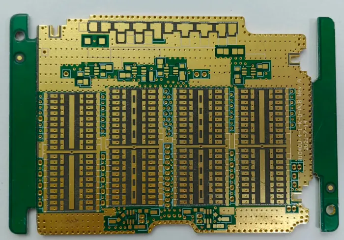
Rogers materials are high-frequency laminates often used in RF and microwave applications due to their low dielectric loss and stable electrical properties. These materials, which include hydrocarbon-based and PTFE-based composites, require careful handling during laser drilling to maintain their performance.
Key Parameters for Rogers:
- Laser Type: UV lasers (355 nm) are preferred for Rogers materials as they provide cleaner cuts with minimal thermal impact.
- Power: Low to moderate power (5-15 W) prevents damage to the delicate dielectric layers.
- Pulse Duration: Ultra-short pulses (nanoseconds) are critical to avoid heat-affected zones (HAZ) that could alter the material’s dielectric constant, typically around 2.2-3.5 for Rogers laminates.
- Repetition Rate: A higher repetition rate (50-100 kHz) ensures smoother hole walls and faster processing.
- Focus Spot Size: A tight focus (15-30 μm) is necessary for precision in high-frequency designs.
Tip: Rogers materials often have copper cladding, so adjust the laser energy to avoid over-penetration or copper damage. Post-drilling inspection for dielectric integrity is also recommended, as even slight thermal damage can impact signal speeds (often in the range of 0.7-0.8 times the speed of light in vacuum for high-frequency designs).
Laser Drilling Parameters for Ceramic PCBs
Ceramic PCBs, often made from materials like alumina (Al2O3) or aluminum nitride (AlN), are used in high-power and high-temperature applications due to their excellent thermal conductivity (up to 170 W/m·K for AlN) and electrical insulation. However, their hardness and brittleness make laser drilling tricky.
Key Parameters for Ceramic PCBs:
- Laser Type: UV lasers (355 nm) or femtosecond lasers are best for ceramics to minimize cracking and thermal stress.
- Power: Higher power (20-30 W) may be needed due to the material’s hardness, but it must be carefully controlled.
- Pulse Duration: Ultra-short pulses (femtoseconds to picoseconds) are essential to avoid micro-cracks in the brittle substrate.
- Repetition Rate: Lower rates (10-30 kHz) help manage heat dissipation in the material.
- Focus Spot Size: A small spot size (10-20 μm) ensures precision without excessive material removal.
Tip: Use a percussion drilling technique (repeated pulses at a single point) for ceramics to gradually remove material without causing fractures. Cooling systems during drilling can also help manage thermal stress.
Laser Drilling Parameters for PTFE
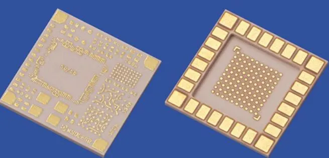
PTFE (polytetrafluoroethylene), also known as Teflon, is a popular material for high-frequency and high-performance PCBs due to its ultra-low dielectric constant (around 2.1) and excellent chemical resistance. However, its soft and heat-sensitive nature requires precise laser control.
Key Parameters for PTFE:
- Laser Type: UV lasers (355 nm) are ideal for PTFE to achieve clean cuts without excessive melting.
- Power: Low power (5-10 W) prevents melting or deformation of the soft material.
- Pulse Duration: Short pulses (nanoseconds) minimize thermal damage to the surrounding area.
- Repetition Rate: Moderate rates (30-60 kHz) balance speed and quality.
- Focus Spot Size: A small spot size (15-25 μm) ensures precision for microvias in high-frequency designs.
Tip: PTFE often has a low glass transition temperature, so maintaining a low heat input is critical. Use a debris removal system to prevent molten material from re-depositing on the PCB surface, which could affect signal integrity.
Suggested Image Placement: Place an image of a PTFE PCB with finely drilled vias. ALT Text: "Finely drilled vias on a PTFE PCB for high-frequency performance."
Laser Drilling Parameters for Metal Core PCBs
Metal core PCBs (MCPCBs) are designed for heat dissipation in high-power applications, featuring a metal base layer (usually aluminum or copper) with a thin dielectric layer. Laser drilling in MCPCBs must account for the high thermal conductivity of the metal (e.g., 200-300 W/m·K for aluminum) and the risk of damaging the dielectric layer.
Key Parameters for Metal Core PCBs:
- Laser Type: Fiber lasers (1064 nm) or UV lasers (355 nm) are suitable for penetrating the dielectric layer without excessive heat transfer to the metal core.
- Power: Moderate to high power (15-25 W) for dielectric removal, with careful control to avoid metal damage.
- Pulse Duration: Short pulses (microseconds to nanoseconds) limit heat transfer to the metal base.
- Repetition Rate: Moderate rates (20-50 kHz) ensure controlled material removal.
- Focus Spot Size: A spot size of 20-40 μm works well for balancing precision and efficiency.
Tip: Drilling through the dielectric layer without penetrating the metal core requires precise depth control. Use a layered drilling approach, adjusting power as you approach the metal interface to avoid short circuits or damage.
General Best Practices for Laser Drilling Optimization
While material-specific parameters are crucial, some general practices can improve laser drilling outcomes across all PCB types:
- Calibration: Regularly calibrate the laser system to maintain focus and power accuracy.
- Testing: Conduct test drills on scrap material to fine-tune parameters before full production.
- Cleaning: Use air or vacuum systems to remove debris during drilling, preventing contamination.
- Inspection: Post-drilling inspection with microscopes or automated optical systems ensures hole quality and dimensional accuracy.
Conclusion
Optimizing laser drilling parameters for different PCB materials is essential for achieving high-quality vias and ensuring the reliability of your printed circuit boards. Whether you're working with FR-4, Rogers, ceramic, PTFE, or metal core PCBs, tailoring settings like laser power, pulse duration, and repetition rate to the material’s properties can make all the difference. By following the guidelines outlined in this blog, you can minimize defects, improve production efficiency, and deliver superior PCBs for a wide range of applications.
At ALLPCB, we’re committed to supporting your manufacturing needs with cutting-edge solutions and expert advice. Use these insights to refine your laser drilling process and take your PCB designs to the next level.


