 ALLPCB


In high-frequency PCB design, every detail matters, especially when it comes to maintaining signal integrity. One often overlooked factor is the surface finish of the PCB. So, how does PCB surface finish affect signal integrity in high-frequency applications? Simply put, the surface finish impacts conductivity, signal loss, and impedance control, which are critical for ensuring signals travel without distortion or degradation at high speeds. In this comprehensive guide, we’ll dive deep into the relationship between PCB surface finish and signal integrity, exploring popular finishes like ENIG and immersion silver, and providing actionable insights for minimizing signal loss in your designs.
Understanding High-Frequency PCB Design and Signal Integrity
High-frequency PCB design involves creating circuits that operate at frequencies typically above 100 MHz, where signals are more susceptible to interference, loss, and distortion. Signal integrity refers to the ability of a signal to maintain its quality as it travels through the PCB, without being affected by noise, crosstalk, or impedance mismatches. Poor signal integrity can lead to data errors, reduced performance, or complete system failure in applications like telecommunications, RF devices, and high-speed digital systems.
In such designs, every element of the PCB, from the materials used to the surface finish, plays a role in preserving signal quality. While high-frequency PCB materials like low-loss laminates are often the focus, the surface finish—the protective coating applied to the copper traces—can significantly influence performance. Let’s explore why this matters and how to choose the right finish for your project.
Why PCB Surface Finish Matters for Signal Integrity
The surface finish on a PCB serves multiple purposes: it protects the copper from oxidation, ensures good solderability, and, in high-frequency designs, influences electrical performance. At high frequencies, signals travel along the surface of conductors due to the skin effect, where current flows primarily near the surface of the trace rather than through its entire cross-section. This makes the surface finish a critical factor in determining conductivity, signal loss, and impedance control.
A poor surface finish can introduce additional resistance, increase insertion loss, or cause uneven impedance, all of which degrade signal integrity. For example, a finish with low conductivity might increase signal loss, while a finish with inconsistent thickness could disrupt impedance matching, leading to reflections and signal distortion. Understanding the impact of different finishes helps designers make informed choices to optimize performance.
Common PCB Surface Finishes and Their Impact on High-Frequency Signals
There are several surface finishes commonly used in PCB manufacturing, each with unique properties that affect signal integrity in high-frequency designs. Below, we’ll examine two popular options—ENIG and immersion silver—and discuss their characteristics in terms of conductivity, insertion loss, and overall performance.
ENIG (Electroless Nickel Immersion Gold) and Insertion Loss
ENIG is a widely used surface finish due to its excellent corrosion resistance, flat surface, and good solderability. It consists of a layer of nickel over the copper, topped with a thin layer of gold. However, when it comes to high-frequency PCB design, ENIG has some drawbacks related to insertion loss—the reduction in signal strength as it passes through a conductor.
The nickel layer in ENIG has ferromagnetic properties, which can increase insertion loss at frequencies above 1 GHz. Studies have shown that ENIG can contribute to a signal loss of approximately 0.2 to 0.5 dB per inch at 10 GHz, depending on the trace geometry and board material. This makes ENIG less ideal for extremely high-frequency applications (e.g., above 20 GHz), where minimizing signal loss is critical. However, for many designs operating below 10 GHz, ENIG remains a reliable choice due to its durability and consistent impedance control.
Immersion Silver and Conductivity
Immersion silver is another popular surface finish, valued for its high conductivity and cost-effectiveness compared to ENIG. Silver has one of the highest electrical conductivities among metals, with a conductivity value of approximately 6.3 x 10^7 S/m, compared to copper’s 5.96 x 10^7 S/m. This makes immersion silver an excellent choice for high-frequency PCB designs where signal loss minimization is a priority.
Unlike ENIG, immersion silver does not introduce a ferromagnetic layer like nickel, resulting in lower insertion loss at high frequencies. Tests indicate that immersion silver can reduce signal loss by up to 20% compared to ENIG at frequencies around 10 GHz. However, silver is prone to tarnishing and oxidation over time, which can degrade performance if not handled or stored properly. Designers must weigh these trade-offs when selecting immersion silver for their projects.
Signal Loss Minimization in High-Frequency PCB Design
Minimizing signal loss is a top priority in high-frequency PCB design, and the choice of surface finish is just one piece of the puzzle. Here are some strategies to reduce insertion loss and ensure signal integrity:
- Choose the Right Surface Finish: As discussed, immersion silver often outperforms ENIG in terms of conductivity and lower insertion loss. For applications above 10 GHz, consider silver or other finishes optimized for high-frequency performance.
- Use Low-Loss Materials: Pair your surface finish with high-frequency PCB materials like PTFE-based laminates, which have dielectric constants (Dk) as low as 2.2 and dissipation factors (Df) below 0.001, reducing signal attenuation.
- Optimize Trace Geometry: Wider traces and smoother copper surfaces reduce resistance and skin effect losses. Surface roughness can increase loss by up to 10-20% at frequencies above 5 GHz, so opt for smoother copper foils when possible.
- Minimize Via Usage: Vias introduce inductance and capacitance, which can distort high-frequency signals. Keep via count low and use back-drilling techniques to remove unused via stubs.
By combining these strategies with an appropriate surface finish, designers can significantly reduce signal loss and improve overall performance.
Impedance Control and Surface Finish: A Critical Connection
Impedance control is another key aspect of high-frequency PCB design, ensuring that signals travel without reflections caused by mismatches in characteristic impedance. The surface finish can subtly affect impedance by altering the effective dielectric constant and conductivity at the trace surface.
For instance, the thin gold layer in ENIG has a negligible effect on impedance due to its minimal thickness (typically 0.05 to 0.1 micrometers). However, the nickel underlayer can slightly increase effective resistance, impacting impedance at very high frequencies. Immersion silver, with its uniform and highly conductive layer, tends to provide more consistent impedance, often within ±5% of the target value (e.g., 50 ohms for RF designs).
To achieve precise impedance control, designers should:
- Collaborate with manufacturers to ensure consistent surface finish thickness.
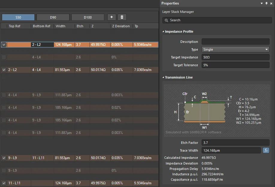
- Use simulation tools to model the impact of surface finish on impedance before fabrication.
- Specify tight tolerances for trace width and spacing, as small variations can compound with surface finish effects.
Other Factors in High-Frequency PCB Design
While surface finish plays a significant role in signal integrity, other factors in high-frequency PCB design must also be considered for optimal performance:
- Dielectric Material Selection: Materials with low Dk and Df values, such as Rogers RO4350B (Dk = 3.48, Df = 0.0037 at 10 GHz), are essential for reducing signal delay and loss.
- Layer Stackup Design: A well-planned stackup with proper ground planes minimizes crosstalk and maintains consistent impedance. For example, a 4-layer stackup with dedicated ground planes can reduce noise by up to 30% compared to a 2-layer design.
- Routing Techniques: Avoid sharp bends in traces, as they can cause signal reflections. Use 45-degree angles or curved traces for smoother signal paths.
Integrating these considerations with the right surface finish creates a robust foundation for high-frequency designs.
Practical Tips for Choosing the Right Surface Finish
Selecting the best PCB surface finish for signal integrity in high-frequency applications requires balancing performance, cost, and environmental factors. Here are some practical tips to guide your decision:
- For frequencies below 5 GHz, ENIG is often sufficient due to its durability and moderate cost. Its insertion loss is manageable in this range, typically less than 0.3 dB per inch.
- For frequencies above 10 GHz, consider immersion silver or alternative finishes like OSP (Organic Solderability Preservative) with enhanced coatings to prioritize conductivity and signal loss minimization.
- Evaluate the operating environment. If the PCB will be exposed to humidity or corrosive conditions, ENIG’s resistance to oxidation makes it a safer choice over immersion silver.
- Work closely with your manufacturing partner to ensure the chosen finish is applied uniformly, as inconsistencies can introduce unexpected signal integrity issues.
Conclusion: Balancing Surface Finish and Signal Integrity
In high-frequency PCB design, achieving optimal signal integrity requires careful attention to every detail, including the often-underestimated role of surface finish. Whether you choose ENIG for its durability or immersion silver for its superior conductivity, understanding the impact of PCB surface finish on signal integrity is essential for minimizing signal loss and ensuring impedance control. By pairing the right finish with high-frequency PCB materials, optimized trace designs, and proper manufacturing practices, you can build reliable, high-performance circuits for even the most demanding applications.


