 ALLPCB


If you're looking for a reliable way to repair or replace Ball Grid Array (BGA) components on a printed circuit board (PCB), you've come to the right place. BGA rework is a specialized process that involves removing, replacing, or repairing these high-density components with precision to ensure functionality and reliability. In this comprehensive guide, we'll walk you through the BGA rework process, from setting up a BGA rework station to mastering BGA stencil application, ensuring proper BGA component alignment, and meticulously inspecting BGA solder joints. Whether you're a seasoned technician or new to PCB repair, this blog will provide actionable insights and advanced techniques to achieve successful results.
What is BGA Rework and Why is it Important?
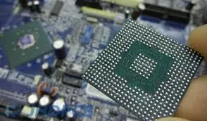
Ball Grid Array (BGA) components are widely used in modern electronics due to their ability to support high-density connections in a compact space. Unlike traditional components with visible pins, BGAs have an array of solder balls underneath that connect to the PCB. While this design offers excellent performance, it also makes repair and replacement challenging. BGA rework is the process of removing a faulty BGA component, preparing the site, and installing a new one with precision.
The importance of BGA rework lies in its ability to save costs and extend the life of a PCB. Replacing an entire board can be expensive, especially in high-value devices like servers, gaming consoles, or industrial equipment. By mastering the BGA rework process, technicians can address issues like cracked solder joints, overheating damage, or manufacturing defects without discarding the entire assembly.
Setting Up a BGA Rework Station: The Foundation of Success
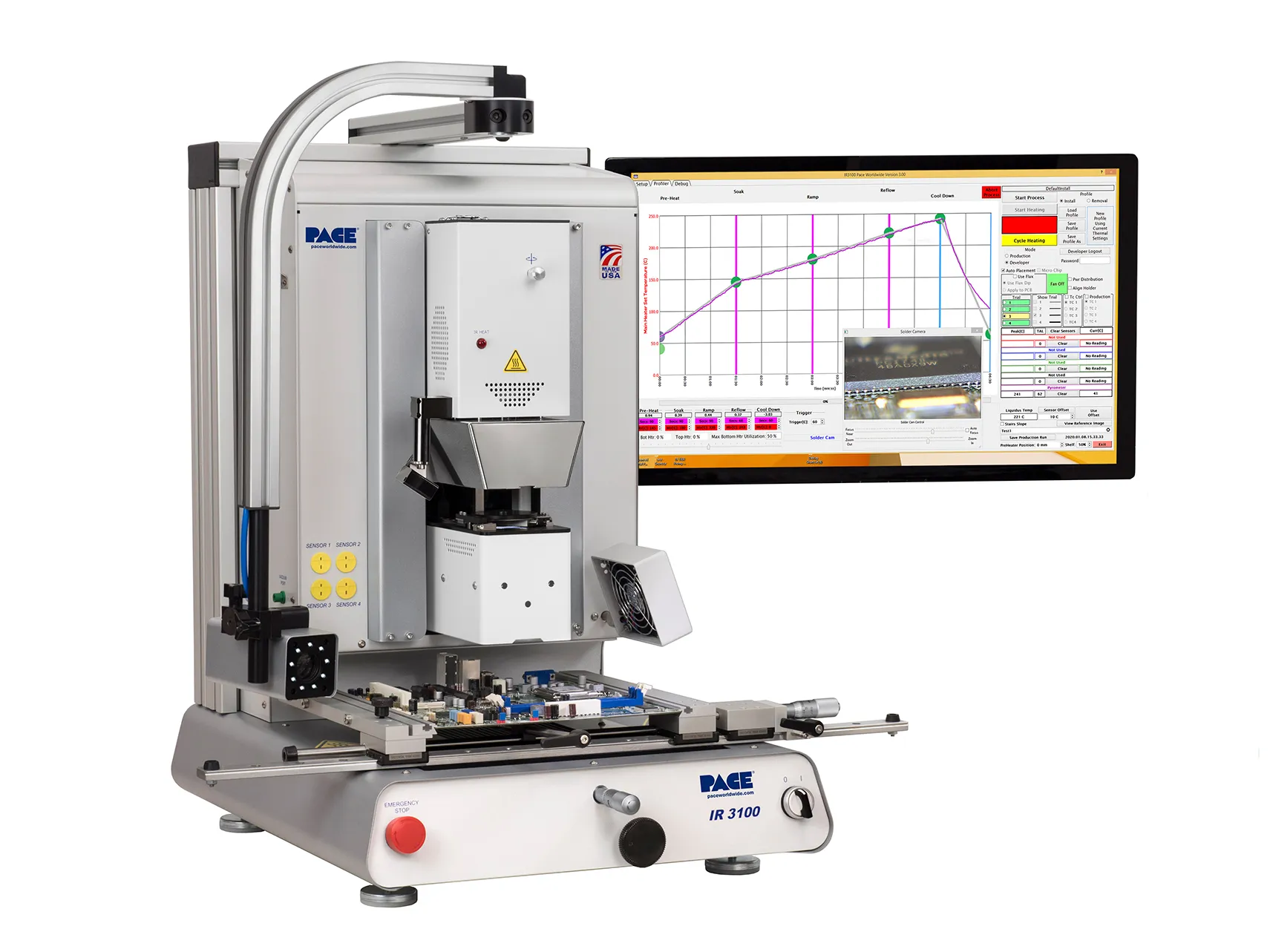
A proper BGA rework station setup is critical for achieving consistent and reliable results. Unlike standard soldering tools, BGA rework requires specialized equipment to handle the delicate nature of these components and the precision needed for their placement and soldering.
Essential Equipment for a BGA Rework Station
- Hot Air Rework Station: This tool provides controlled heat to melt solder balls during removal and reflow. Look for a station with adjustable temperature (typically 200°C to 400°C) and airflow settings to prevent damage to nearby components.
- Infrared (IR) Preheater: A preheater warms the PCB from below to reduce thermal stress and ensure even heating. This is crucial for larger boards to avoid warping.
- Vision System or Microscope: A high-resolution camera or microscope helps with BGA component alignment by magnifying the tiny solder balls and pads, ensuring accurate placement.
- Temperature Probes: These monitor the temperature of the PCB and component during the rework process to prevent overheating.
- Flux and Cleaning Supplies: Flux aids in solder flow, while isopropyl alcohol and brushes are needed for cleaning the site after rework.
Steps for Setting Up Your Station
- Position the rework station on a stable, ESD-safe workbench to prevent static damage.
- Place the IR preheater under the PCB holder to ensure uniform heating of the board.
- Set up the hot air tool with the appropriate nozzle size for the BGA component (nozzles typically range from 10mm to 40mm depending on component size).
- Calibrate the vision system to focus on the BGA site for precise alignment.
- Keep all tools, including tweezers and solder paste, within easy reach for efficiency.
Mastering the BGA Rework Process: Step-by-Step Guide
The BGA rework process involves several critical steps, each requiring attention to detail to avoid damaging the PCB or component. Below, we break down the process into manageable stages.
Step 1: Preparation and Assessment
Before starting, evaluate the PCB and BGA component to identify the issue. Common problems include cracked solder joints (often due to thermal stress) or component failure. Use an X-ray inspection system if available to check for hidden defects in the solder joints. Ensure you have the replacement BGA component and necessary tools ready.
Step 2: Removing the Faulty BGA Component
Use the hot air rework station to heat the BGA component evenly. Set the temperature to approximately 300°C-350°C (depending on the solder type, such as lead-free or leaded) and apply heat for 30-60 seconds. The goal is to melt the solder balls underneath without overheating nearby components. Once the solder is molten, gently lift the BGA using tweezers or a vacuum pickup tool.
Step 3: Site Preparation
After removal, clean the PCB pads using a soldering iron and wick to remove excess solder. Apply flux to the site and use isopropyl alcohol with a brush to remove any residue. Inspect the pads under a microscope to ensure they are clean and undamaged. If pads are lifted or damaged, they may need repair before proceeding.
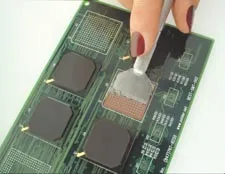
Step 4: Applying Solder Paste with a Stencil
BGA stencil application is a crucial step to ensure the correct amount of solder is applied to each pad. Use a mini stencil designed for the specific BGA component. Align the stencil over the PCB pads and secure it with tape or a holder. Spread a thin layer of solder paste (typically a lead-free alloy with a melting point of around 217°C) across the stencil using a squeegee. Remove the stencil carefully and inspect the paste deposits under a microscope to confirm uniformity.
Step 5: Aligning and Placing the New BGA Component
Proper BGA component alignment is essential for a successful rework. Place the new BGA component onto the prepared site using a vision system or microscope to align the solder balls with the PCB pads. Modern rework stations often have split-screen vision systems that overlay the component and board for precise alignment. Ensure the component is perfectly centered before proceeding to reflow.
Step 6: Reflowing the Solder
Use the hot air rework station to reflow the solder paste. Preheat the PCB using the IR preheater to around 150°C to minimize thermal shock. Then, apply hot air at 300°C-350°C to the BGA component for about 45-60 seconds. The solder paste will melt and form connections between the BGA balls and PCB pads. Allow the board to cool gradually to prevent stress on the joints.
Step 7: Cleaning and Final Touches
After reflow, clean the area around the BGA with isopropyl alcohol and a brush to remove flux residue. Inspect the component to ensure it is securely attached and there are no visible defects.
Inspecting BGA Solder Joints: Ensuring Quality and Reliability
Inspecting BGA solder joints is a critical final step in the rework process. Since the solder joints are hidden beneath the component, traditional visual inspection is not possible. Instead, advanced techniques are required to verify the integrity of the connections.
Methods for Inspecting BGA Solder Joints
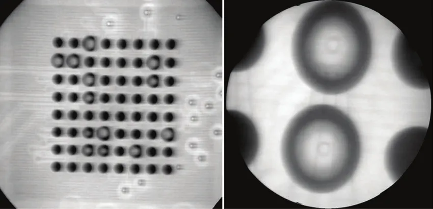
- X-Ray Inspection: Automated X-ray inspection (AXI) is the most effective method for examining BGA solder joints. It can detect voids (air bubbles in the solder, ideally less than 25% of joint area), bridging (unintended connections between joints), and insufficient solder. X-ray systems can penetrate the component to provide a clear image of the joint quality.
- Endoscope Inspection: For smaller setups without X-ray equipment, an endoscope camera can be used to inspect the outer edges of the BGA for alignment and solder flow issues.
- Functional Testing: After inspection, test the PCB to ensure the BGA component functions as expected. This may involve powering on the device and running diagnostic software to check for connectivity issues.
Common Issues in BGA Solder Joints
- Voids: Excessive voids can weaken the joint and cause reliability issues. Aim for void percentages below 25% as per industry standards like IPC-7095.
- Bridging: Solder bridges between adjacent balls can cause short circuits. This often results from excessive solder paste during BGA stencil application.
- Cold Joints: If the reflow temperature is too low (below 217°C for lead-free solder), the solder may not fully melt, leading to weak connections.
Advanced Techniques for BGA Rework
For those looking to take their BGA rework skills to the next level, consider these advanced techniques to improve precision and efficiency.
Thermal Profiling
Create a thermal profile for your rework station based on the specific PCB and BGA component. Use temperature probes to monitor the heating and cooling rates during reflow. A typical profile for lead-free solder includes a preheat stage (150°C for 60 seconds), a soak stage (180°C-200°C for 30 seconds), and a reflow stage (peak at 240°C for 20-40 seconds). This minimizes thermal stress and ensures consistent results.
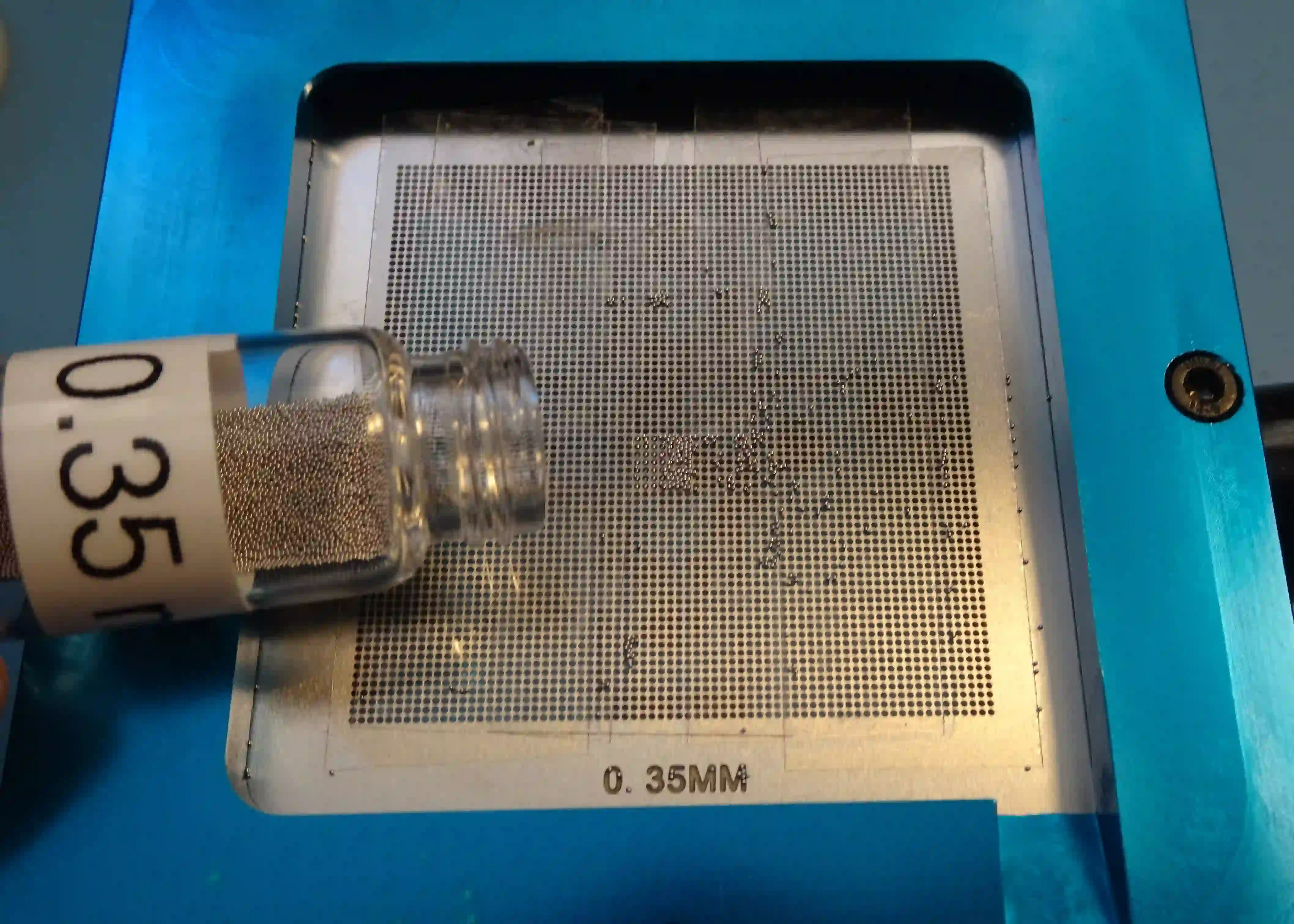
Reballing BGA Components
In some cases, the BGA component itself can be reused by replacing its solder balls, a process known as reballing. Use a reballing kit with a stencil and new solder balls (typically 0.3mm to 0.6mm in diameter depending on the component). Align the stencil over the BGA, apply solder balls, and reflow them using a hot air station. This technique is cost-effective for expensive components.
Using Nitrogen Gas for Reflow
For high-reliability applications, introduce nitrogen gas during the reflow process. Nitrogen reduces oxidation of the solder joints, resulting in stronger and more durable connections. This is especially useful for lead-free solder, which is more prone to oxidation at high temperatures.
Common Challenges in BGA Rework and How to Overcome Them
BGA rework is a complex process with several potential pitfalls. Here are some common challenges and tips to address them.
- Warping of the PCB: Excessive heat can cause the board to warp, misaligning pads. Use a preheater to distribute heat evenly and avoid rapid cooling.
- Damage to Adjacent Components: Protect nearby components with heat-resistant tape or shields during rework to prevent unintended reflow or damage.
- Poor Alignment: If BGA component alignment is off, the solder joints will fail. Invest in a high-quality vision system and take time to double-check placement before reflow.
Conclusion: Elevating Your BGA Rework Skills
BGA rework is a valuable skill for any electronics technician or engineer, enabling cost-effective repairs and extending the life of critical PCBs. By following the detailed steps outlined in this guide—from BGA rework station setup and BGA stencil application to precise BGA component alignment and thorough inspecting BGA solder joints—you can achieve professional-grade results. Incorporate advanced techniques like thermal profiling and reballing to further enhance your capabilities.
At ALLPCB, we understand the importance of precision in electronics manufacturing and repair. Our resources and expertise are here to support you in mastering the BGA rework process and tackling even the most challenging projects with confidence. Keep practicing, stay updated with the latest tools and techniques, and you'll be well on your way to becoming a BGA rework expert.


