 ALLPCB


If you're looking to master G-10 PCB SMT and G-10 PCB through-hole assembly, you've come to the right place. This guide dives deep into advanced techniques for assembling G-10 PCBs, covering both Surface Mount Technology (SMT) and through-hole methods. We'll explore practical tips for soldering, component placement, and optimizing your workflow for reliability and efficiency. Whether you're a seasoned engineer or a hobbyist stepping into advanced PCB assembly, this post offers actionable insights to elevate your projects.
What Makes G-10 PCBs Unique?
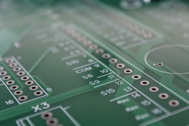
G-10 is a high-pressure fiberglass laminate material widely used in PCB manufacturing due to its excellent electrical insulation properties and mechanical strength. Often referred to as a type of FR-4 material, G-10 is known for its durability, resistance to moisture, and ability to handle high temperatures, making it ideal for demanding applications. However, working with G-10 PCBs requires specific techniques due to its rigidity and thermal characteristics, especially during G-10 PCB advanced assembly.
Unlike softer or more flexible materials, G-10 can be less forgiving when it comes to drilling or soldering errors. Its high thermal resistance means it can withstand soldering temperatures, but it also requires precise heat management to avoid delamination or damage. Understanding these properties is the foundation for successful SMT and through-hole assembly on G-10 boards.
Surface Mount Technology (SMT) for G-10 PCBs
SMT is a popular choice for modern electronics due to its ability to support smaller, denser component layouts. When working with G-10 PCB SMT, precision and proper equipment are key to achieving reliable connections without damaging the board.
Key Steps in SMT Assembly for G-10 PCBs
1. Solder Paste Application: Start by applying solder paste to the pads using a stencil. Ensure the stencil aligns perfectly with the PCB to avoid misalignment. For G-10 boards, use a lead-free solder paste with a melting point around 217-220°C to match the board's thermal tolerance.
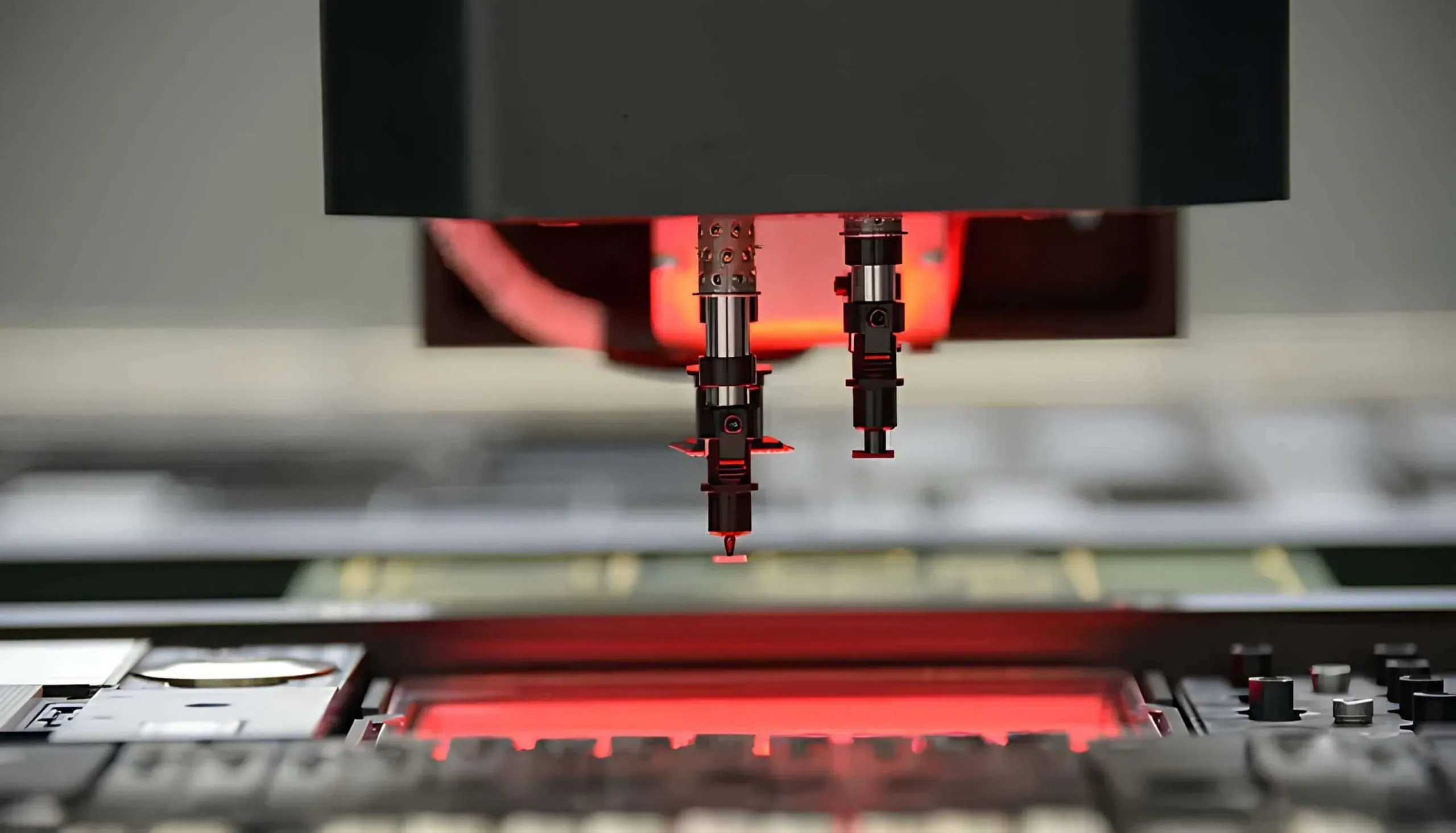
2. Component Placement: Use a pick-and-place machine or tweezers for manual placement of components. G-10's smooth surface can make components slide if not secured properly, so double-check alignment before soldering. Aim for a placement accuracy of ±0.1 mm for fine-pitch components.
3. Reflow Soldering: During reflow, maintain a controlled temperature profile. Preheat the board to 150°C for 60-90 seconds, then ramp up to a peak of 235-245°C for no more than 30 seconds. G-10 can handle these temperatures, but prolonged exposure risks warping.
4. Inspection: After soldering, inspect for cold joints or bridging using a magnifying glass or automated optical inspection (AOI). G-10's rigidity can sometimes cause uneven heat distribution, leading to soldering defects if not monitored.
Tips for SMT on G-10 PCBs
- Use a low-residue flux to prevent buildup on the board's surface, as G-10 can be harder to clean compared to other materials.
- For high-density layouts, consider a double-sided reflow process to maximize space, ensuring the board cools completely between cycles to avoid thermal stress.
- Maintain a clean workspace. Dust or debris on G-10 can interfere with solder paste application due to its non-porous nature.
Through-Hole Assembly Techniques for G-10 PCBs
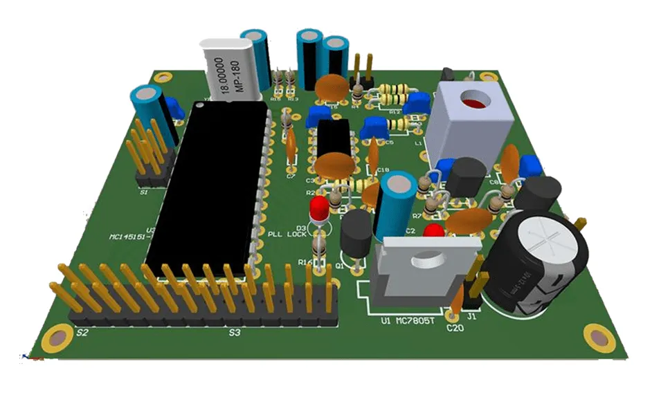
While SMT dominates modern designs, G-10 PCB through-hole assembly remains essential for components requiring robust mechanical connections, such as connectors or high-power devices. G-10's strength makes it an excellent candidate for through-hole applications, but careful handling is necessary to avoid damaging the board during drilling or soldering.
Key Steps in Through-Hole Assembly for G-10 PCBs
1. Drilling and Preparation: Drill holes with a carbide bit at a speed of 10,000-15,000 RPM to prevent chipping. G-10 is tough, so use a steady hand or a drill press for precision. Clean holes with compressed air to remove debris.
2. Component Insertion: Insert components manually or with automated equipment, ensuring leads are straight and fit snugly. G-10's rigidity means misaligned holes can make insertion difficult, so measure twice before drilling.
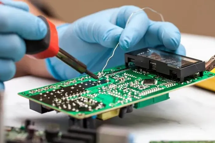
3. Soldering: Use a soldering iron with a temperature of 300-350°C for through-hole joints. Apply heat for no more than 3-5 seconds per joint to avoid overheating the board. Use a 60/40 tin-lead solder or lead-free alternative with a flux core for better flow.
4. Trimming and Cleaning: After soldering, trim excess leads with flush cutters and clean the board with isopropyl alcohol to remove flux residue. G-10's surface resists staining, but thorough cleaning ensures long-term reliability.
G-10 PCB Soldering Tips for Through-Hole
- Pre-tin component leads before insertion to improve solder flow and reduce heat exposure on the board.
- For larger components, use a wave soldering machine if available. Set the wave temperature to 260°C and adjust conveyor speed to ensure even soldering without thermal shock.
- Avoid excessive force when inserting components. G-10 can crack under stress if holes are too tight or components are forced.
Advanced Component Placement Strategies for G-10 PCBs
Effective G-10 PCB component placement is critical for both SMT and through-hole assembly. Poor placement can lead to signal interference, thermal issues, or manufacturing challenges. Here are advanced strategies tailored for G-10 boards.
Optimizing Layout for Signal Integrity
G-10 PCBs are often used in high-frequency applications due to their low dielectric constant (around 4.5-5.0 at 1 MHz). To maintain signal integrity:
- Place high-speed components close to each other to minimize trace length. Aim for trace lengths under 10 mm for signals above 100 MHz.
- Route power and ground planes adjacent to signal layers to reduce electromagnetic interference (EMI). Use vias sparingly on G-10, as excessive drilling can weaken the board.
- Separate analog and digital components to avoid crosstalk. Maintain at least 2 mm spacing between these sections.
Thermal Management in Component Placement
G-10 has moderate thermal conductivity, so heat dissipation must be planned during layout design:
- Position heat-generating components, like power ICs, near the board's edges or areas with good airflow. Avoid clustering them in the center.
- Use thermal vias under high-power SMT components to transfer heat to the opposite side of the board. Space vias at 1.2-1.5 mm intervals for optimal heat distribution.
- For through-hole components, ensure heatsinks are securely mounted with proper clearance (at least 5 mm) from other parts to prevent overheating nearby components.
Common Challenges in G-10 PCB Assembly and How to Overcome Them
Assembling G-10 PCBs can present unique challenges due to the material's properties. Here's how to tackle some common issues during G-10 PCB advanced assembly.
Thermal Stress During Soldering
G-10 can withstand high temperatures, but uneven heating can cause stress or delamination. To prevent this, always use a preheating stage before reflow or wave soldering. Keep temperature gradients below 2°C per second during heating and cooling phases.
Drilling Precision for Through-Hole
The hardness of G-10 makes drilling errors costly. Invest in high-quality drill bits and use a drill press for consistent results. If a hole is slightly misaligned, avoid forcing components through, as this can crack the board. Instead, re-drill with caution or redesign the layout if necessary.
Component Misalignment in SMT
G-10's smooth surface can cause components to shift during SMT assembly. Use a small amount of adhesive under larger components before reflow to hold them in place. Additionally, ensure your pick-and-place equipment is calibrated for accuracy within ±0.05 mm.
Tools and Equipment for G-10 PCB Assembly
Having the right tools can make a significant difference in the quality of your G-10 PCB SMT and through-hole assembly. Here are some essentials:
- Soldering Station: A temperature-controlled station with adjustable settings (250-400°C) for both SMT and through-hole soldering.
- Reflow Oven: For SMT, a benchtop reflow oven with programmable profiles ensures consistent results on G-10 boards.
- Drill Press: For through-hole assembly, a drill press with variable speed control (up to 15,000 RPM) prevents damage to G-10 material.
- Magnifying Tools: A 10x magnifying glass or digital microscope helps inspect solder joints and component alignment.
- ESD Protection: Use anti-static mats and wrist straps to protect sensitive components during assembly.
Best Practices for Quality Assurance
Quality control is vital in G-10 PCB advanced assembly to ensure reliability in the final product. Follow these practices:
- Perform a visual inspection after each assembly stage to catch defects early. Look for solder bridges, misaligned components, or cracks in the G-10 material.
- Use electrical testing to verify connections. For high-frequency G-10 PCBs, test impedance with a network analyzer to ensure it matches design specs (typically 50 ohms for RF traces).
- Document your process. Keep a log of soldering temperatures, drilling speeds, and inspection results to identify patterns in defects and improve future assemblies.
Conclusion: Elevating Your G-10 PCB Assembly Skills
Mastering G-10 PCB through-hole and G-10 PCB SMT assembly takes practice, precision, and the right techniques. By understanding the unique properties of G-10 material, optimizing component placement, and following advanced soldering tips, you can achieve high-quality results for even the most complex projects. Whether you're working on high-frequency designs or robust mechanical connections, these strategies will help you build reliable and efficient G-10 PCBs.
With the actionable advice provided in this guide, you're well-equipped to tackle G-10 PCB advanced assembly challenges. Keep refining your skills, invest in quality tools, and prioritize precision at every step. Your next G-10 PCB project could be your best one yet.


