 ALLPCB


Are you looking to improve the efficiency and quality of your printed circuit board (PCB) separation process? PCB depaneling, the process of separating individual boards from a larger panel, is a critical step in manufacturing. Choosing the right method and following best practices can save time, reduce costs, and prevent damage to delicate components. In this guide, we’ll dive into a detailed PCB depaneling methods comparison, explore PCB depaneling best practices, and share tips for depaneling process optimization, depaneling quality control, and minimizing stress in depaneling. Let’s get started with everything you need to know to optimize this essential step in PCB production.
What is PCB Depaneling and Why Does It Matter?
PCB depaneling is the process of separating individual circuit boards from a larger panel after they’ve been manufactured together. Panels are used to streamline production, reduce handling, and lower costs by allowing multiple boards to be processed at once. However, separating these boards without causing damage or stress to components is crucial for maintaining functionality and reliability.
A poor depaneling process can lead to cracked boards, damaged traces, or stressed components, which might result in failures during testing or in the field. By optimizing depaneling, manufacturers can improve yield rates, reduce waste, and ensure high-quality end products. Let’s explore the various methods available and how to choose the best one for your needs.
PCB Depaneling Methods Comparison: Finding the Right Fit
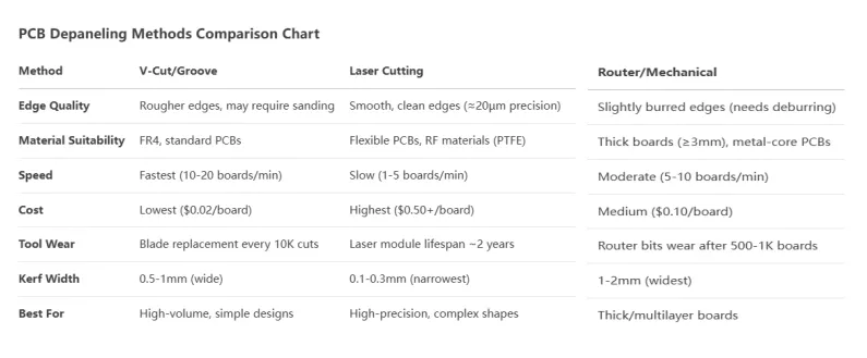
There are several methods for depaneling PCBs, each with its own advantages and limitations. Understanding these options is key to selecting the right approach for your project. Below, we’ll compare the most common techniques based on precision, speed, cost, and suitability for different board types.
1. Manual Depaneling
Manual depaneling involves breaking apart PCBs by hand, often along pre-scored lines or V-cuts. This method is simple and requires minimal equipment, making it cost-effective for low-volume production or prototyping.
- Pros: Low cost, no specialized tools needed, ideal for small batches.
- Cons: High risk of stress on components, inconsistent results, not suitable for complex or delicate boards.
- Best For: Simple designs with thick boards and no sensitive components near edges.
2. V-Cut Scoring and Breaking
V-cut depaneling uses a machine to create V-shaped grooves along separation lines during manufacturing. Boards are then snapped apart manually or with a tool. This method is widely used due to its balance of cost and efficiency.
- Pros: Affordable, faster than manual methods, works well for straight-line separations.
- Cons: Can cause mechanical stress, limited to linear cuts, not ideal for intricate designs.
- Best For: Medium-volume production with rectangular boards.
- Stress Impact: Stress levels can reach up to 300 microstrain near V-cut edges if not done carefully, potentially affecting nearby components.
Suggested Reading: Automated Depaneling vs. Manual Breakaway: Which Method is Right for You?
3. Router Depaneling
Router depaneling uses a CNC machine with a rotating bit to cut through tabs or connections holding boards together. This method offers higher precision than V-cut or manual techniques.
- Pros: High accuracy, suitable for complex shapes, minimal stress when optimized.
- Cons: Slower process, generates dust that requires cleanup, higher equipment cost.
- Best For: High-mix, low-to-medium volume production with irregular board shapes.
- Speed: Typical cutting speeds range from 50 to 100 mm/s, depending on material thickness (e.g., 1.6 mm FR4 boards).
4. Laser Depaneling
Laser depaneling uses a focused laser beam to cut through PCBs with extreme precision. This non-contact method is gaining popularity for its ability to handle delicate and complex designs.
- Pros: No mechanical stress, clean cuts, excellent for thin or flexible PCBs.
- Cons: High initial investment, slower for thick boards, requires specialized setup.
- Best For: High-value, high-precision applications like medical or aerospace electronics.
- Precision: Lasers can achieve cut widths as narrow as 20-30 micrometers, reducing material waste.
Suggested Reading: Laser PCB Depaneling: Achieving High Precision and Minimal HAZ
5. Punching or Die-Cutting
Punching involves using a custom die to stamp out individual boards from a panel. It’s a fast method for high-volume production but requires upfront tooling costs.
- Pros: Very fast for large runs, consistent results.
- Cons: High tooling cost, potential for stress on boards, limited to specific designs.
- Best For: Mass production of simple, uniform board shapes.
PCB Depaneling Best Practices for Optimal Results
Selecting the right depaneling method is just the first step. Following best practices ensures consistent quality and minimizes risks. Here are actionable tips for depaneling process optimization and beyond.
1. Design Panels with Depaneling in Mind
The depaneling process starts at the design stage. Consider these design tips to make separation easier and safer:
- Place V-cuts or tabs away from sensitive components to avoid stress. A minimum clearance of 5 mm from components to cut lines is often recommended.
- Use rounded corners on tabs to reduce stress concentration during separation.
- Ensure panel borders are at least 5-10 mm wide for stability during processing.
2. Choose the Right Method for Your Board Type
Match the depaneling method to your PCB’s material, thickness, and complexity. For example:
- Thin boards (under 1 mm) benefit from laser cutting to avoid bending or cracking.
- Thicker boards (over 2 mm) may work well with V-cut or router methods if precision isn’t critical.
- Flexible PCBs require non-contact methods like laser to prevent tearing.
3. Control Environmental Factors
Dust, vibration, and static electricity can affect depaneling quality. Implement these controls:
- Use dust extraction systems during router depaneling to prevent contamination of components.
- Minimize vibrations by securing panels properly during cutting or punching.
- Ground equipment to avoid static discharge, which can damage sensitive electronics.
4. Test and Iterate
Before full-scale production, test your depaneling setup on a small batch. Check for issues like edge roughness, component stress, or misalignments. Adjust parameters like cutting speed or laser power accordingly. For instance, reducing router speed from 100 mm/s to 75 mm/s can decrease edge stress by up to 20% on FR4 material.
Depaneling Quality Control: Ensuring Consistency and Reliability
Quality control is non-negotiable in PCB depaneling. Even minor defects can lead to costly rework or product failures. Here’s how to maintain high standards with depaneling quality control.
1. Inspect Edges for Damage
After depaneling, inspect board edges for cracks, burrs, or delamination. Use a microscope or automated optical inspection (AOI) systems to detect defects as small as 10 micrometers. Rough edges can affect board fitment in enclosures or lead to trace damage over time.
2. Measure Stress Levels
Mechanical stress during depaneling can weaken solder joints or components. Use strain gauges to measure stress near cut lines. Aim to keep stress below 200 microstrain to avoid long-term reliability issues. If stress is too high, consider switching to a gentler method like laser cutting.
3. Verify Dimensional Accuracy
Ensure separated boards meet dimensional tolerances using calipers or coordinate measuring machines (CMM). Deviations as small as 0.1 mm can cause assembly issues in tight-fit applications. For high-precision needs, laser depaneling often achieves tolerances of ±0.05 mm.
4. Document and Standardize Processes
Create detailed standard operating procedures (SOPs) for depaneling. Include parameters like cutting speed, tool settings, and inspection criteria. Regularly train staff to follow these SOPs to maintain consistency across production runs.
Minimizing Stress in Depaneling: Protecting Your Boards
One of the biggest challenges in depaneling is minimizing stress in depaneling to protect components and ensure reliability. Stress can cause micro-cracks, solder joint failures, or component detachment. Here are proven strategies to reduce stress.
1. Optimize Tab Design and Placement
Tabs (also called mouse bites) are small connection points holding boards in a panel. Design tabs with small perforations (e.g., 0.5 mm holes) to make breaking easier. Limit the number of tabs to 3-5 per board edge to reduce force needed during separation.
2. Use Fixtures and Supports
During depaneling, use custom fixtures to hold panels securely without flexing. For V-cut breaking, support the board on both sides of the cut line to prevent uneven stress distribution. This can cut stress levels by up to 30% compared to unsupported breaking.
3. Slow Down Mechanical Processes
For methods like routing or punching, slower speeds reduce vibration and stress. While this may increase cycle time, the trade-off is often worth it for high-value boards. For example, lowering router speed from 100 mm/s to 60 mm/s can decrease stress near edges by 15-20%.
4. Consider Non-Contact Methods
If stress remains a concern despite optimization, switch to laser depaneling. Since there’s no physical contact, stress is virtually eliminated, making it ideal for boards with high component density near edges.
Depaneling Process Optimization: Boosting Efficiency
Optimizing the depaneling process goes beyond quality—it’s also about efficiency. Here’s how to streamline operations with depaneling process optimization.
1. Automate Where Possible
Automated depaneling systems, like CNC routers or laser cutters, reduce human error and speed up production. For high-volume runs, automation can cut cycle times by 40-50% compared to manual methods.
2. Minimize Setup Time
Use standardized panel designs to reduce setup changes between batches. For router depaneling, pre-program cutting paths to avoid manual adjustments. This can save up to 10-15 minutes per setup in medium-volume production.
3. Balance Cost and Quality
While advanced methods like laser cutting offer superior results, they’re not always cost-effective for low-budget projects. Evaluate the cost-per-board impact of each method. For instance, V-cut depaneling might cost $0.10 per board, while laser could be $0.50 or more.
4. Integrate with Assembly Workflow
Plan depaneling to align with PCB assembly steps. Separate boards just before final assembly to minimize handling damage. Alternatively, depanel after testing if boards need to remain in panel form for automated testing equipment.
Conclusion: Mastering PCB Depaneling for Better Results
Optimizing PCB depaneling is a game-changer for PCB manufacturers aiming to improve quality, reduce costs, and boost efficiency. By understanding the strengths and weaknesses of each method—whether it’s manual breaking, V-cut scoring, routing, laser cutting, or punching—you can make informed decisions tailored to your project’s needs. Implementing PCB depaneling best practices, focusing on depaneling quality control, and prioritizing strategies for minimizing stress in depaneling will ensure your boards remain intact and reliable.
Take the time to design panels thoughtfully, test your processes, and invest in the right tools for the job. With these steps, you’ll master depaneling process optimization and deliver high-quality PCBs every time. Stay tuned for more insights and tips on streamlining your manufacturing journey!


