ALLPCB


Overview
Fingerprint authentication is increasingly used in identity verification. The fingerprint authentication examination system described here collects, stores, recognizes, and verifies personal fingerprint information via a fingerprint module, and manages identity information centrally. The system uses students' fingerprints to verify identity. The data center must download fingerprint data to each fingerprint handheld device, and each handheld must upload its recorded information back to the data center for centralized candidate management. Choosing a suitable data transmission method for the handheld device is therefore important.
Wired networks require significant cabling work, are prone to damage, have lower reliability, and are harder to maintain. They also occupy more space. For short transmission distances, wireless transmission can meet requirements while avoiding these wired-network drawbacks. This project uses the single-chip wireless transceiver nRF905 to build a master-slave, point-to-multipoint wireless data transmission system.
1 Hardware design
The wireless transmission system consists of a data center, a wireless data transceiver, and multiple handheld terminals. The wireless data transceiver and the data center communicate via RS232 serial communication. The data center acts as the master station and the handheld devices act as slave stations; each handheld device and the wireless data transceiver communicate bidirectionally over wireless links.
Before an examination, the data center at the academic administration department queries each handheld in turn through the wireless data transceiver, downloading the necessary candidate and exam-room information. Proctors verify student identity using student numbers and fingerprints in sequence, and record absences, substitutions, late arrivals, and cheating incidents on the handheld devices. After the exam, proctors submit the handheld devices to the academic administration department, and the data center processes the uploaded data from the handhelds.
The handheld hardware is mainly composed of a main controller PIC18F6520, a 4x5 keypad, a display S6B0724, a serial EEPROM, external data storage, a real-time clock circuit DS1302, a power supply circuit, the nRF905 wireless interface circuit, and a fingerprint module (SM-L6Z). The wireless data transceiver hardware is similar: PIC18F6520, serial EEPROM, external storage, power circuit, nRF905 wireless interface circuit, and an RS232 interface circuit for communication with the data center.
2 nRF905 wireless transceiver overview
The nRF905 wireless communication chip operates in the 433/868/915 MHz bands and does not require a license. The exact operating frequency can be configured by the connected microcontroller. It uses optimized GMSK modulation and supports a maximum data rate of 100 kb/s (Manchester encoded). The nRF905 integrates power management, a crystal oscillator, a low-noise amplifier, a frequency synthesizer, and a power amplifier. Its supply voltage range is 1.9 to 3.6 V. Antennas can be a PCB loop antenna or a single-ended whip antenna. Transmit power is up to +10 dBm and receive sensitivity is specified as 460 dBm in the source text; open-field transmission range can generally exceed 600 m, though range is reduced in complex terrain and depends on environment, interference, and system tuning. Typical practical tuning should not exceed 200 m.
The nRF905 communicates with a microcontroller via SPI. It automatically handles packet preamble and CRC. The microcontroller provides the data and the receiver address to the nRF905; the nRF905 packages the data with preamble and CRC and transmits. On receive, carrier detect (CD) and address match (AM) pins are available. When a correct packet is received, the nRF905 strips preamble, address, and CRC and notifies the microcontroller to fetch the data. In standby mode the nRF905 consumes about 40 uA; in power-down mode the source text specifies 2.5 A. In standby and power-down modes it cannot transmit or receive, but it can be configured via SPI, enabling energy-efficient operation.
The nRF905-to-MCU interface circuit is shown in Figure 1.
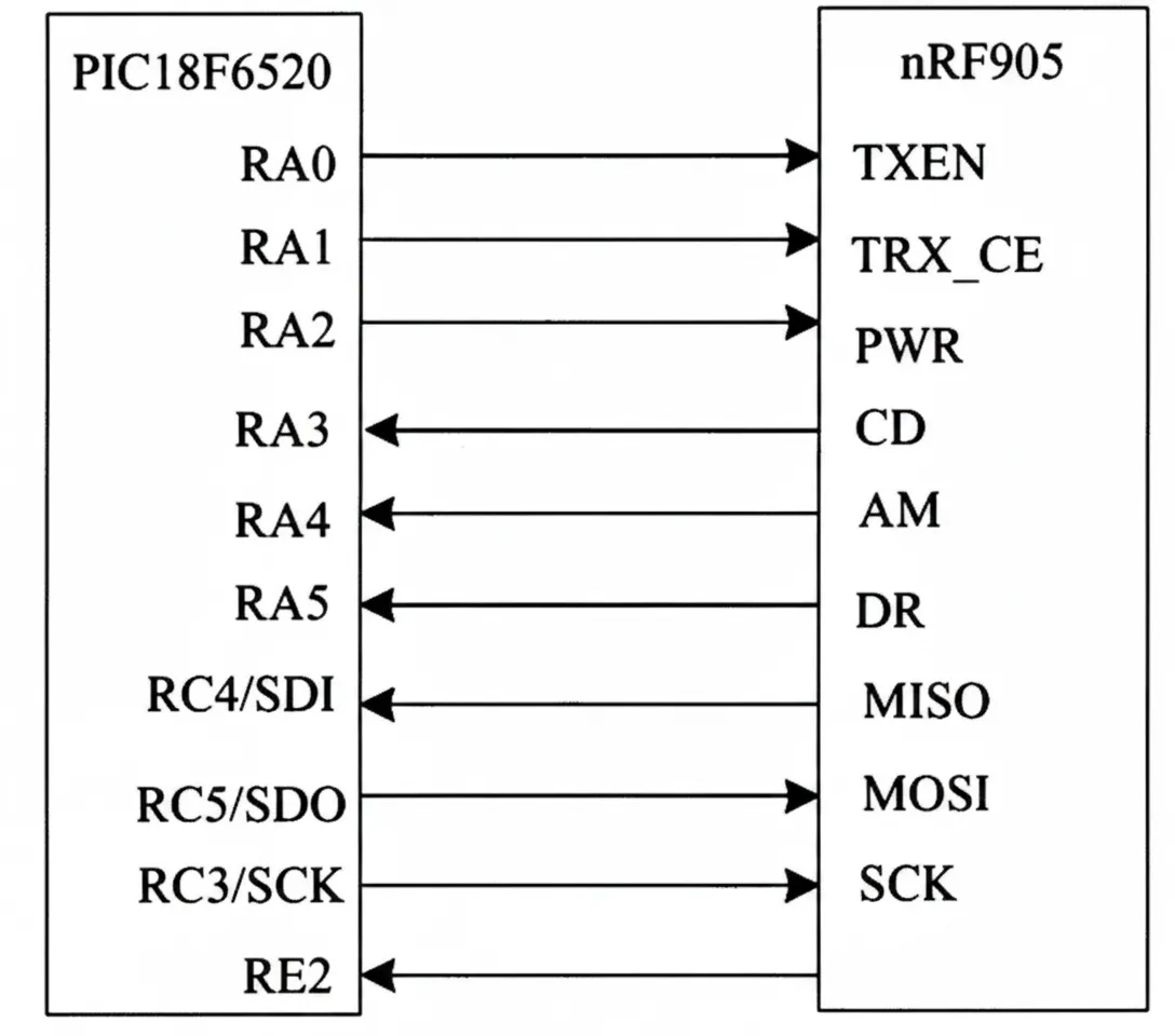
Figure 1 nRF905 and MCU interface circuit
3 Star topology point-to-multipoint transmission
The system forms a wireless LAN composed of the wireless data transceiver and the data center plus multiple handheld nodes, using a star topology to implement point-to-multipoint data transmission. The transmission link distribution, where 00 (the wireless data transceiver and the data center) is the host, and 01–n are the handheld nodes. This topology is suitable for high-data-volume scenarios with tight timing requirements, for short-range transmission, and for environments with strong interference.
The nRF905 supports half-duplex transmission. The host and each node have unique addresses. During transmission the current sender acts as the master and receivers act as slaves. The master scans slave addresses and performs one-to-one transfers with each slave. Thus, point-to-multipoint communication is realized as a sequence of point-to-point transfers. The master includes the destination slave address in the data frame; each slave compares the received address with its own address and only accepts packets addressed to itself, preventing incorrect reception by other nodes.
Each nRF905 also has an inherent address code to identify itself. Separately, the host and nodes have network identifiers used to identify them within the local network. These two address types serve different purposes: the nRF905 address code identifies the transceiver itself, while the network identifier identifies the device within the LAN.
4 Data transmission protocol and software
4.1 Data packet protocol
To improve reliability in noisy environments, testing found that the sequence 0xFF followed by 0xAA, 0x55 rarely occurs in noise. The protocol therefore prefixes packets with start bytes 0xFF, 0xAA, 0x55. Because the first byte can be lost during transmission, the actual transmitted sequence can include a preceding arbitrary byte, then 0xFF followed by 0xAA, 0x55. The receiver accepts only packets beginning with 0xFF, 0xAA, 0x55. The packet format is shown in Figure 2.

Figure 2 Data packet format
The header is 0xFF, 0xAA, 0x55. HOST is the master address, LOCAL is the slave address, LENGTH is the data length, DATA1...DATAN are the payload bytes, and CHECK is the checksum. When the MCU sends this packet to the nRF905, the nRF905 will automatically add its own preamble and CRC before transmission.
4.2 Data transfer procedure
Transmission between sender and receiver uses a handshake mechanism. The sender acts as master; receivers act as slaves. Upon entering the receive routine, the slave reads the address sent by the master and compares it with its own address. If it does not match, the slave is not the target and sets the nRF905 to receive mode to wait for the next address. If it matches, the slave returns its address as an acknowledgment to complete the handshake with the master. After handshake success, the slave receives the data and verifies the checksum. If verification fails, the slave requests retransmission and returns to receive the data again. If verification succeeds, the slave processes the data and then returns to wait for the next packet.
Conclusion
The system uses wireless transmission to support the design of a fingerprint authentication handheld device. The wireless data transmission system is compact and convenient and can correctly transmit fingerprint data, providing a practical application example for fingerprint recognition technology.