ALLPCB


1. Experimental principle
Previously we discussed a 51 microcontroller-based stepper motor control experiment; the principle here is similar.
First, a brief introduction to the 42-stepper motor. A 42-stepper motor is a common type of stepper motor that converts pulse signals into mechanical rotation. The 42-stepper motor is typically driven in two-phase or four-phase configurations; each phase has a coil. This article covers a two-phase, four-wire stepper motor. By sequentially energizing different coils, the motor rotates by discrete step angles. These motors are widely used in automation and mechanical systems such as printers, CNC machines, and textile machinery. They have simple structure, convenient control, and good positioning accuracy.
Note the arrangement of the two-phase windings and the meaning of the four wires A+, A-, B+, B-, and key parameters such as step angle (1.8°) and rated current (1.0A).
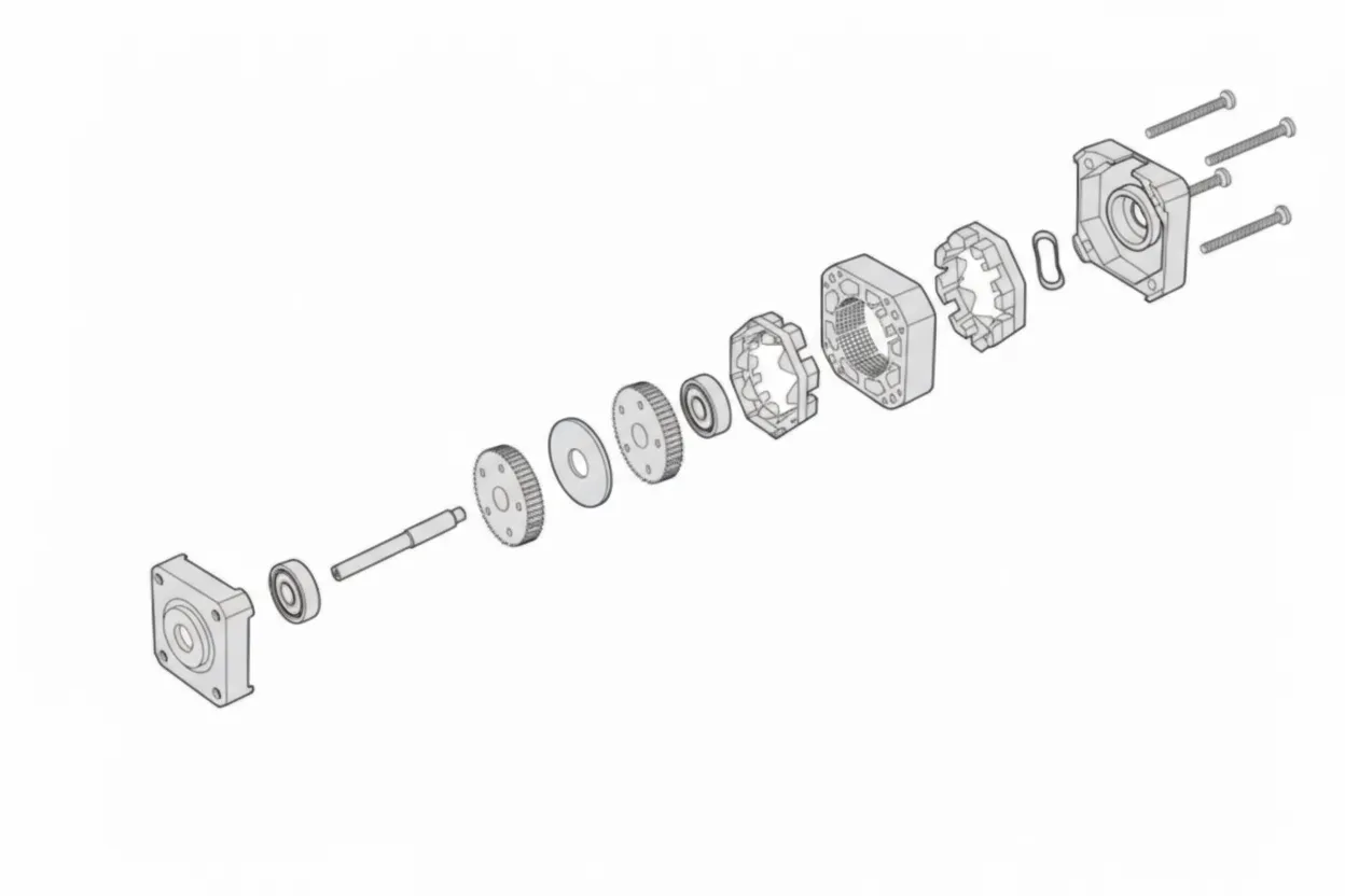
2. Construction and internal structure
The internal construction of a stepper motor, after disassembly, is shown below:
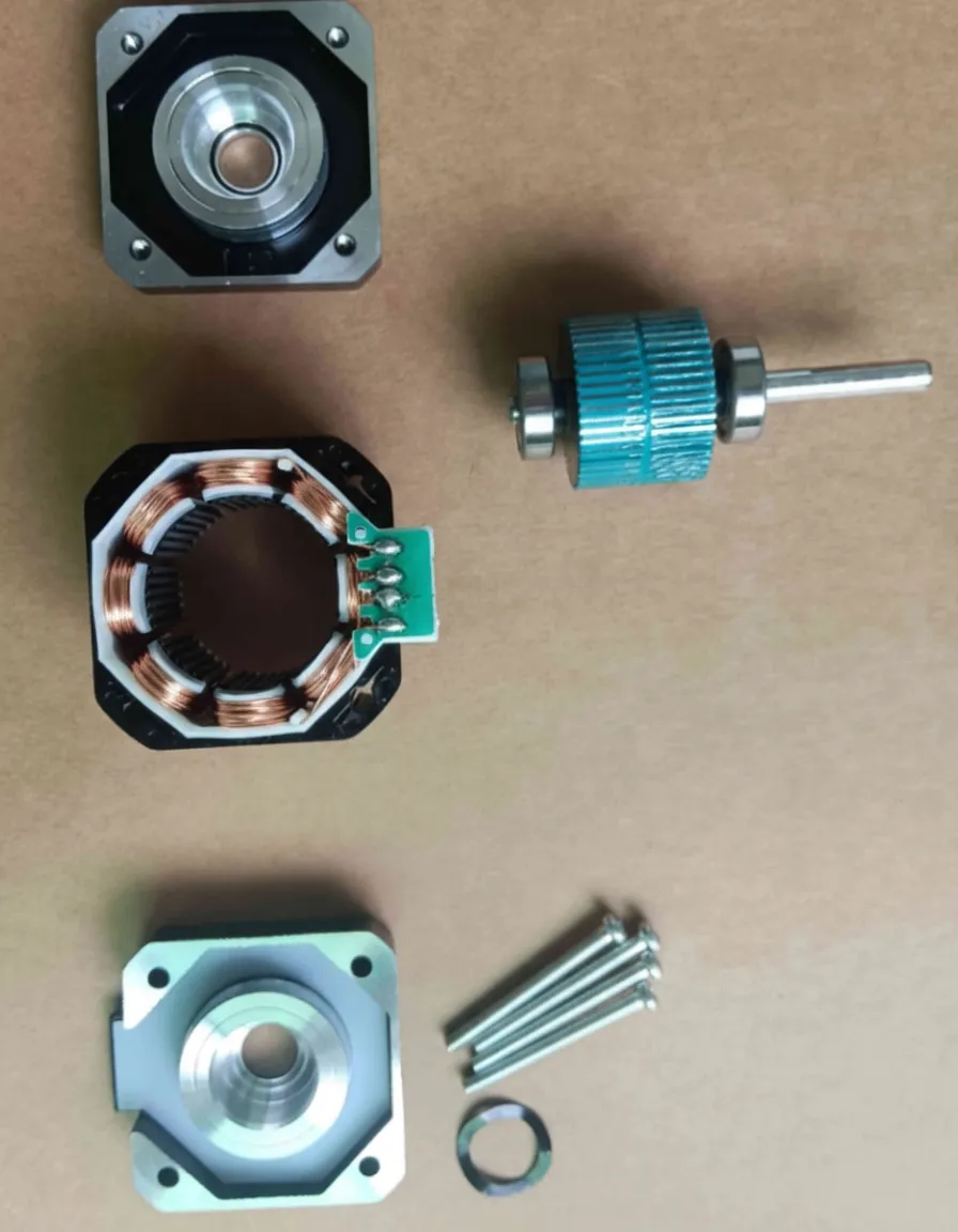
The 42-stepper motor has a step angle of 1.8°, determined by the tooth counts of the stator and rotor. The stator has 48 teeth and the rotor has 50 teeth; the calculation follows from those numbers. The focus here is on how to make the stepper motor rotate.
3. Rotation principle
The simplified diagram of the stator and rotor is shown below:
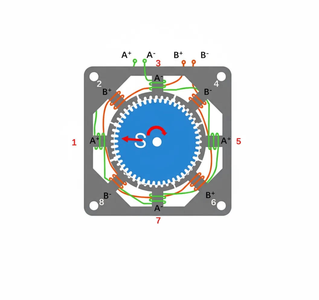
The stator is divided into eight groups, each group containing six teeth, for a total of 48 teeth. The rotor has 50 teeth. Windings 1, 3, 5, and 7 belong to one winding line, and windings 2, 4, 6, and 8 belong to the other. Hence the motor is two-phase: A+ and A- form phase A, while B+ and B- form phase B. The winding arrangement makes opposite coils in the same phase have the same magnetic polarity while adjacent coils have opposite polarities. For example, if coils 1 and 5 in phase A are south poles, then coils 3 and 7 are north poles; phase B follows the same arrangement.
Stepper motors operate by magnetic forces: like poles repel and unlike poles attract. Starting from position 1 and moving clockwise, the control sequence is explained below.
1) To align the stator teeth at position 1 with the rotor teeth, the coil at position 1 must present a north pole near the rotor, so it attracts the rotor to that position. Using the right-hand rule, set A+ high, A- low, and both B+ and B- low.
2) At this time the next stator position (position 2) is 1.8° away. To align position 2, set B+ high, B- low, and both A+ and A- low. The rotor rotates clockwise by 1.8°.
3) To align position 3, set A- high, A+ low, and both B+ and B- low. The rotor rotates another 1.8° clockwise.
4) To align position 4, set B- high, B+ low, and both A+ and A- low. The rotor rotates another 1.8° clockwise.
5) To align position 5, set A+ high, A- low, and both B+ and B- low. This repeats the cycle from positions 1 to 4.
The table below shows the phase levels corresponding to these positions:
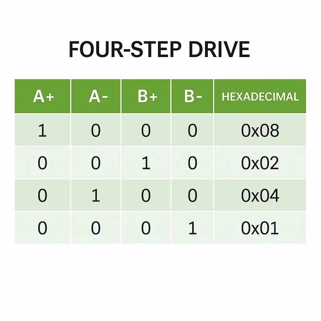
The above method is a four-step (full-step) drive. The motor advances by the full step angle of 1.8° each step. To achieve smaller steps, use an eight-step (half-step) drive. In the half-step mode, the motor can stop at positions between the full steps, yielding a half-step angle of 0.9°. For example, to position the rotor between positions 1 and 2, energize both A+ and B+ so the rotor is held in equilibrium between the two attracting forces. In that case set A+ high, A- low, B+ high, B- low.
Speed control is achieved by timing. If the rotor is held at position 1 for a delay time before moving to the next position, that delay controls the rotational speed: longer delays reduce speed, shorter delays increase speed. The delay should be chosen within the motor's acceptable range based on its characteristics.
With the above principles, the driving program can be written accordingly.
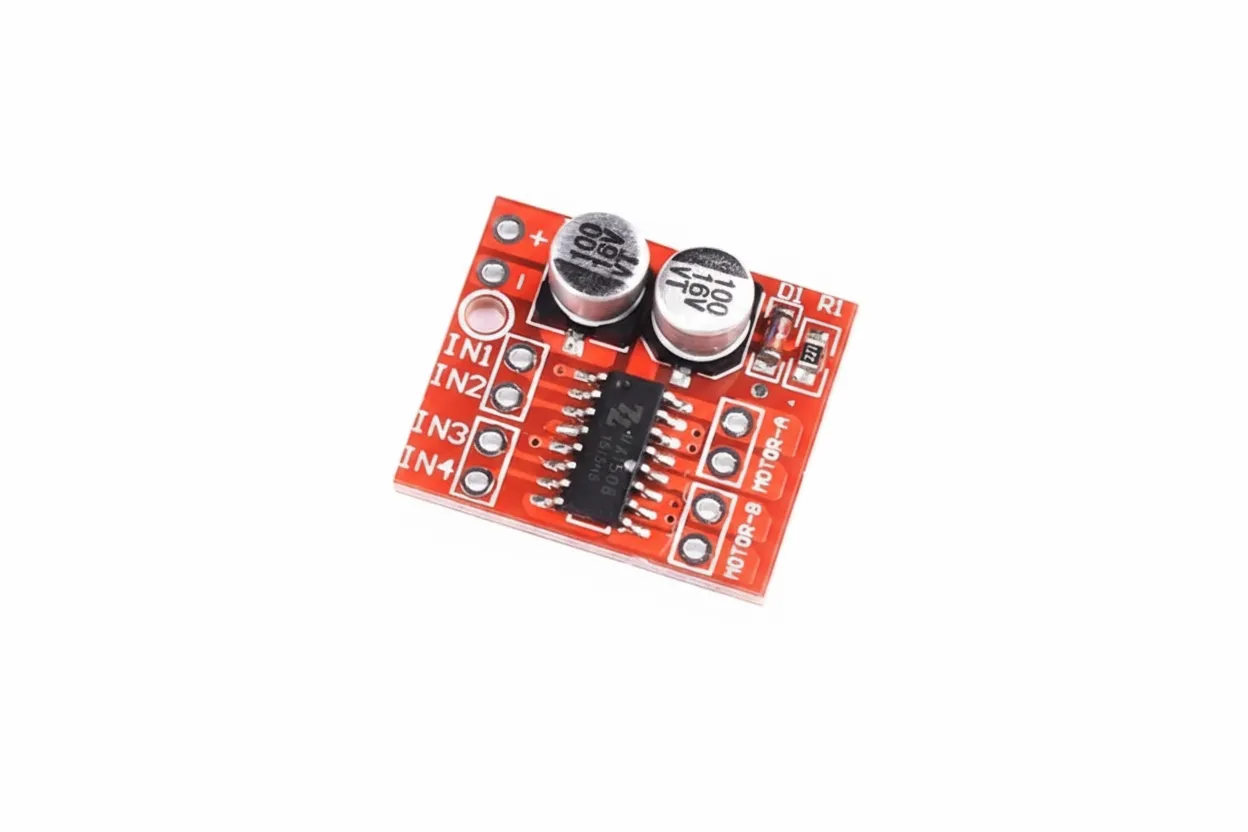
4. Stepper motor driver board (L298N)
The driver used in this experiment is the L298N. It is commonly used for basic demonstrations. Below are its basic specifications. Note that the power supply voltage must be within the required range.
5. Possible issues during the experiment
1) How to identify A+, A-, B+, B-?
Method 1: When purchasing a stepper motor, wire color codes may be provided. Common color conventions are: red A+, blue A-, green B+, black B-, although variants exist. Often green and black form one phase and red and blue form the other.
Method 2: Because phase A and phase B are wound as separate coils, use a multimeter on the ohms range to measure resistance. Wires belonging to the same phase show low resistance (a few ohms); wires from different phases show open circuit (very high resistance). After identifying the two wires of a phase, naming A+ vs A- is arbitrary.
Method 3: Connect one wire to each of the remaining three in turn and manually rotate the motor. If rotation becomes notably harder when a specific pair is connected, those two wires belong to the same phase.
2) The program is correct but the motor does not turn?
Most likely a wiring issue. Verify phase identification and wiring; swapping the two wires of a phase or swapping phases may resolve the problem.
6. Key program
/*
 dir: rotation direction    enum type
 speed: rotation speed
*/
// Speed control:
void stepper(unsigned int dir, unsigned int speed)
{
  if(dir == Pos)// forward rotation
  {
    //step1:
    IN1_HIGH;IN2_LOW;IN3_LOW;IN4_LOW;Delay(speed);
    //step2:
    IN1_HIGH;IN2_LOW;IN3_HIGH;IN4_LOW;Delay(speed);
    //step3:
    IN1_LOW;IN2_LOW;IN3_HIGH;IN4_LOW;Delay(speed);
    //step4:
    IN1_LOW;IN2_HIGH;IN3_HIGH;IN4_LOW;Delay(speed);
    //step5:
    IN1_LOW;IN2_HIGH;IN3_LOW;IN4_LOW;Delay(speed);
    //step6:
    IN1_LOW;IN2_HIGH;IN3_LOW;IN4_HIGH;Delay(speed);
    //step7:
    IN1_LOW;IN2_LOW;IN3_LOW;IN4_HIGH;Delay(speed);
    //step8:
    IN1_HIGH;IN2_LOW;IN3_LOW;IN4_HIGH;Delay(speed);
  }
  else  // reverse rotation
  {
    //step1:
    IN1_HIGH;IN2_LOW;IN3_LOW;IN4_HIGH;Delay(speed);
    //step2:
    IN1_LOW;IN2_LOW;IN3_LOW;IN4_HIGH;Delay(speed);
    //step3:
    IN1_LOW;IN2_HIGH;IN3_LOW;IN4_HIGH;Delay(speed);
    //step4:
    IN1_LOW;IN2_HIGH;IN3_LOW;IN4_LOW;Delay(speed);
    //step5:
    IN1_LOW;IN2_HIGH;IN3_HIGH;IN4_LOW;Delay(speed);
    //step6:
    IN1_LOW;IN2_LOW;IN3_HIGH;IN4_LOW;Delay(speed);
    //step7:
    IN1_HIGH;IN2_LOW;IN3_HIGH;IN4_LOW;Delay(speed);
    //step8:
    IN1_HIGH;IN2_LOW;IN3_LOW;IN4_LOW;Delay(speed);
  }
}
// Key routine:
unsigned char Key()
{
  unsigned char KeyNumber=0;
  if(P3_1==0){Delay(1000);while(P3_1==0);Delay(1000);KeyNumber=1;}
  if(P3_0==0){Delay(1000);while(P3_0==0);Delay(1000);KeyNumber=2;}
  if(P3_2==0){Delay(1000);while(P3_2==0);Delay(1000);KeyNumber=3;}
  if(P3_3==0){Delay(1000);while(P3_3==0);Delay(1000);KeyNumber=4;}
  return KeyNumber;
}
// Main function: implements stepper motor start/stop, accelerate/decelerate, forward/reverse rotation.
void main()
{
  while(1)
  {
    stepper(dir, speed);
    KeyNum=Key();
    if(KeyNum==1)// toggle direction
    {
     dir = ~dir;
    }
    if(KeyNum==2)// accelerate
   {
     speed-=30;
     if(speed <= 50)speed = 50;
     i=speed;
   }
    if(KeyNum==3)// decelerate
   {
     speed+=30;
     if(speed >= 170)speed = 170;
     i=speed;
   }
    if(KeyNum==4)// start/stop
    {
      flag=~flag;
      if(flag==0)speed=0;
      else speed=i;
    }
  }
}
The code above corresponds to the eight-step phase level table and implements start/stop, speed up/down, and forward/reverse control of the stepper motor.