ALLPCB


Introduction
Power electronics use in industry is increasing for low-scale applications such as battery chargers and LED drivers, and for large-scale applications such as photovoltaic (PV) systems and electric vehicles. Power systems typically include three parts: generation, transmission lines, and distribution. Traditionally, low-frequency transformers have been used for electrical isolation and voltage matching, but 50/60 Hz transformers are large and heavy. Power converters are used to make older and newer power systems compatible by employing the solid-state transformer (SST) concept. SSTs incorporate a high-frequency or medium-frequency power converter to reduce transformer size and increase power density compared with legacy transformers.
Advances in magnetic materials with high flux density, high power capability, and low losses at elevated frequency have enabled SSTs with high power density and efficiency. Most research has focused on conventional two-winding transformers. Growth in distributed generation and the development of smart grids and microgrids have motivated the multiport solid-state transformer (MPSST) concept.
Multiport SST Topology
Each converter port employs a dual-active-bridge (DAB) converter that uses the transformer leakage inductance as the converter inductance. Eliminating separate inductors reduces size and losses. Leakage inductance depends on winding placement, core geometry, and coupling coefficient, which complicates transformer design. Phase shift is used in DAB converters to transfer power from one port to another, but in an MPSST the phase shift of one port affects power flows at other ports. Control complexity therefore increases with the number of ports; most MPSST research focuses on three-port systems.
Design Overview
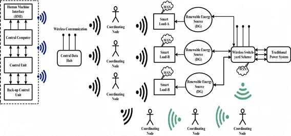
This article describes the design of an SST for microgrid applications. The transformer presented is a four-port device integrated on a single core. The transformer operates at 50 kHz and each port is rated for 25 kW. The port selection models a practical microgrid composed of the utility grid, energy storage, PV, and a load, with the grid port operating at 4.16 kV AC and the other three ports at 400 V.
Transformer Core and Winding Selection
The design objective was to select a material capable of supporting 25 kW per port at a switching frequency of 50 kHz. Commercial core materials include silicon steel, amorphous alloys, ferrite, and nanocrystalline materials. Based on the comparison, nanocrystalline and ferrite were shortlisted. Because nanocrystalline cores exhibit increased losses above about 20 kHz for this application, ferrite was selected as the core material for the transformer.
Core geometry also affects compactness, power density, volume, and especially leakage inductance. For a 330 kW, 50 Hz two-port transformer, shell-type cores and enclosure designs were compared and shell-type configurations were shown to offer lower leakage inductance and smoother power flow. Consequently, a shell-type configuration is used here, with all four windings stacked together on the middle leg to increase the coupling coefficient.
The shell core dimensions are 186 × 152 × 30 mm, using ferrite 3C94 in the specified geometry. Litz wire is used for the medium-voltage (MV) windings; current ratings are 3.42 A and 62.5 A for selected windings. For the low-voltage (LV) ports, 16 AWG and 4 AWG conductors are used. Winding the LV conductors together improves coupling.
Simulation
The proposed MV MPSST design was simulated using Maxwell 3D and SimExplorer. Port voltages for the MV grid, storage, load, and PV ports were modeled as 7.2 kV DC and 400 V DC for storage, load, and PV. Simulations were run at full load to deliver 25 kW at the load port, operating at 50 kHz with a 50% duty cycle. Power control was achieved by phase shifting between converters. Results for different core shapes, cross-sectional areas, and loss characteristics were compared. Model 7 showed lower leakage inductance and higher efficiency.
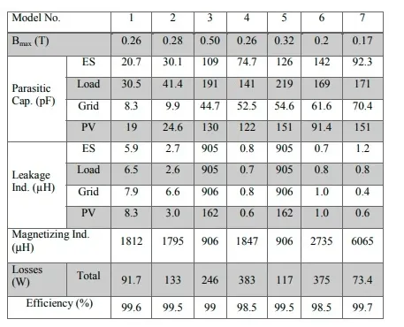
Models and simulation results
Experimental Setup
The prototype core layer uses four U-cores. The magnetic core is assembled in three layers with windings applied on the middle leg. The three low-voltage port windings are wound together. A single DAB converter was used to test the proposed transformer. SiC MOSFETs were used in the converter design. For the medium-voltage port, the rectifier bridge was implemented with SiC diodes and a resistor bank to support the 7.2 kV level.
Conclusion
This work describes the design of a four-port MV MPSST transformer intended for microgrid applications, enabling the interconnection of four different loads or power sources. One transformer port is an MV port supporting 4.16 kV AC. Different core models and materials were evaluated. A test setup was designed for both MV and LV ports. Measured efficiency reached 99%.