ALLPCB


Overview
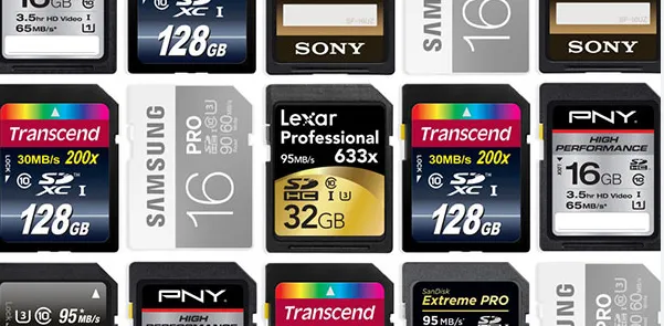
SD card is a low-cost, non-volatile storage format developed by the SD Association. Unlike RAM, SD cards retain data when power is removed. With rapid advances in electronic technology this century, demand for mid-capacity, low-power, space-efficient storage devices has grown.
Speed Classes
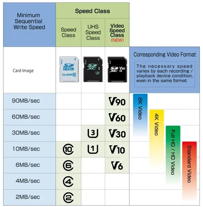
SD cards are classified by speed class. Common speed classes include Class 2 (approx. 2 MB/s), Class 4 (approx. 4 MB/s), Class 6 (up to 6 MB/s), and Class 10 (up to 10 MB/s). SDHC cards support higher speeds, while SDXC cards operate at even higher transfer rates; video speed classes can reach up to about 90 MB/s.
Related Reading: Introduction to Removable SD Card Storage
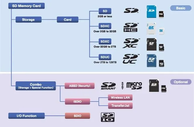
Form Factors
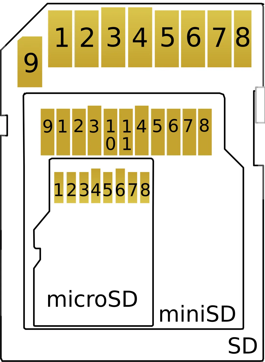
SD cards are available in multiple form factors: standard SD, miniSD, and microSD.
Capacities
Standard SD cards typically provide up to 4 GB. SDHC extends capacity up to 64 GB. SDXC increases capacity further, reaching terabyte-class sizes in some products.
Interfaces and Pinout
SD cards can operate in SD bus mode or SPI bus mode. They are commonly driven by an SDIO or SPI interface. The following pinout shows a typical microSD connector:
| Pin | Name | Signal Function |
|---|---|---|
| 1 | DAT2 | Data bit 2 |
| 2 | CD / DAT3 | Card detect / Data bit 3 |
| 3 | CMD | Command line |
| 4 | Vdd | Supply voltage 2.7 V to 3.6 V |
| 5 | Clk | Clock |
| 6 | VS | Ground |
| 7 | DAT0 | Data bit 0 |
| 8 | DAT1 | Data bit 1 |
Protocol
In the SD protocol, command and data lines are separate. It is necessary to understand both the command transfer format and the data transfer format.
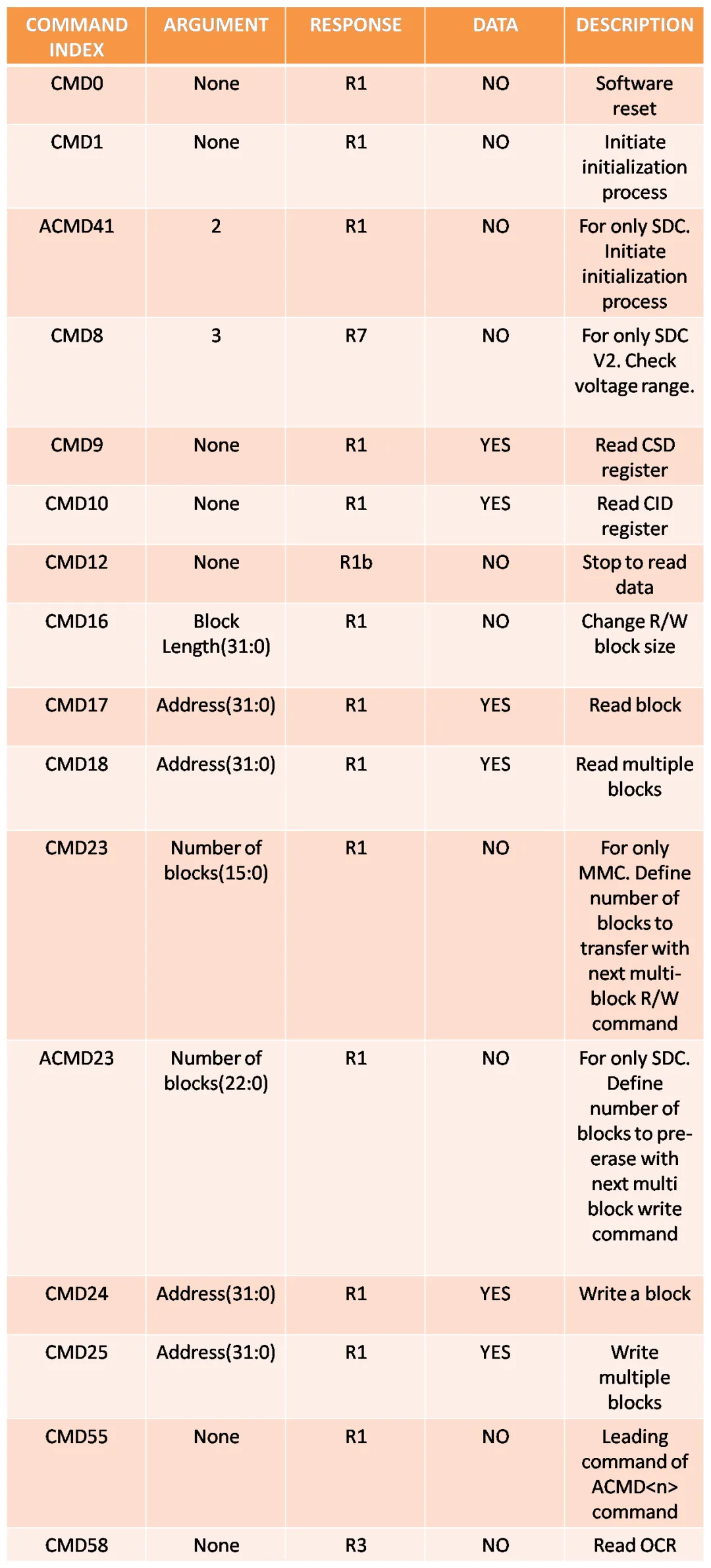
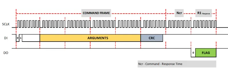
Command Transfer
Commands are sent via the bidirectional CMD pin as 48-bit packets. Each command packet includes a command index, a 32-bit argument, and CRC bits. Commands are always issued by the host and received by the SD card. Responses are also 48 bits long in some cases.
Each command has a fixed length of 6 bytes. The first byte is the command number plus 64. For example, CMD0: command number 0 + 64 = 64 = 0x40. CMD1: 1 + 64 = 65 = 0x41. The next four bytes form the 32-bit argument, often containing an address or block length. The final byte is the CRC byte. If CRC is disabled, most commands in SPI mode do not require a valid CRC. Some commands, such as CMD0, expect a specific CRC (0x95), while many transfers use 0xFF when CRC checking is not enforced. If CRC is enabled, the host must send the correct CRC byte.
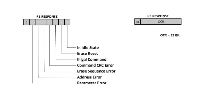
The R1 response byte uses bit fields to report card status. R1 = 0x01 indicates the card is in idle state; R1 = 0x00 means the command was accepted. Other bits indicate specific error or status conditions described in the SD specification.
Data Transfer
During data transfer, the basic unit is a block, typically 512 bytes, transferred over the data pins. A 16-bit CRC is sent after each block. SD cards operate in defined states, each with its own supported command set; the host controls state transitions. Command and data signals are synchronized by the clock. Initial communication typically uses a 400 kHz clock, after which the host increases the clock rate for higher efficiency during data transfers.
During initialization the host does not know whether a connected device is an SD card or an MMC card. MMC typically uses open-drain mode during initialization (100–400 kHz), while SD uses push-pull mode (0–25 MHz). Using a 400 kHz initial clock preserves compatibility with both modes.
Related Reading: PCB Design for USB Interfaces: Ensuring Reliable Data Transfer
Hardware Design
SDIO
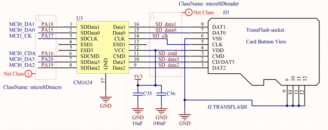
The following is an example 4-bit connection from an SD/MMC peripheral to an SD card slot, using Data[3..0], CLK and CMD signals.
Because card slots are exposed to the external environment, they can be affected by static charge from handling. To meet EMC requirements, designers should apply filtering and protections to avoid conducted and radiated emissions. The SD specification also recommends pull-up resistors and series resistors for impedance matching.
Integrated solutions exist that combine EMI filtering, line termination and ESD protection for microSD/T-Flash interfaces. For example, CM1624 integrates EMI filtering and line termination with TVS diode protection for T-Flash / microSD interfaces.
SPI Mode
In SPI mode, the SD card is connected according to SD Association guidelines using MISO, MOSI, CLK and CS signals.
In both SDIO and SPI modes, data and clock signals operate at high data rates. To avoid signal integrity issues, propagation delays must be considered so that data is stable at the interface before clocked reads or writes. Data signal trace lengths should be matched within fractions of a millimeter; clock length can be slightly longer (approximately 1 mm). To reduce crosstalk, maintain a good ground plane beneath and around these traces and use sufficient vias to connect ground planes between layers.
Summary
This article summarizes SD card classifications and common attributes, outlines the SD protocol, and provides example circuits for SPI and SDIO interfaces. Due to length constraints, software-level topics are not covered here.