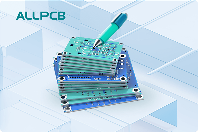
If you're looking for effective ways to design a PCB stackup for analog, digital, or mixed-signal circuits, you're in the right place. A well-planned PCB stackup is crucial for ensuring signal integrity, reducing noise, and maintaining performance in your designs, whether you're working on an analog PCB, a digital PCB, or a mixed-signal PCB. In this comprehensive guide, we'll walk you through the essential guidelines for designing PCB stackups, focusing on layer arrangement, noise isolation techniques, and best practices tailored for different circuit types.
Designing a PCB stackup involves determining the number of layers, their order, and the materials used to separate them. For analog circuits, the focus is on minimizing interference and maintaining clean signals. For digital circuits, high-speed signals and power distribution are key. In mixed-signal designs, noise isolation becomes critical to prevent digital noise from affecting sensitive analog components. Let's dive into the details of how to achieve optimal performance for each type of circuit.
Understanding PCB Stackup Basics
A PCB stackup refers to the arrangement of copper layers and insulating materials (dielectrics) in a printed circuit board. The stackup design directly impacts signal integrity, electromagnetic interference (EMI), and power distribution. A typical stackup includes signal layers, power planes, and ground planes, with the number of layers varying based on the complexity of the design.
For simple designs, a 2-layer or 4-layer stackup might suffice. However, for high-speed digital or sensitive analog circuits, a 6-layer or 8-layer stackup is often necessary to provide dedicated planes for power and ground, which help in noise isolation. The goal is to create a structure that minimizes crosstalk, controls impedance, and ensures reliable operation.
Key Considerations for Analog PCB Stackup Design
Analog circuits are highly sensitive to noise and interference, so the stackup design for an analog PCB must prioritize signal purity. Here are the main guidelines to follow:
1. Use Dedicated Ground Planes
A solid ground plane is essential for analog circuits as it provides a low-impedance path for return currents and helps shield sensitive signals from noise. Place a continuous ground plane directly below the analog signal layer to minimize loop areas and reduce EMI. For a 4-layer board, a common stackup might look like this:
- Top Layer: Analog Signals
- Inner Layer 1: Ground Plane
- Inner Layer 2: Power Plane
- Bottom Layer: Additional Signals or Ground
This arrangement ensures that analog signals have a nearby reference plane, reducing noise pickup.
2. Separate Analog and Digital Grounds
In designs where analog and digital circuits coexist, keep their ground planes separate to prevent digital switching noise from coupling into analog signals. Connect the two grounds at a single point, often near the power supply entry, to avoid ground loops. This technique is vital for noise isolation in mixed-signal designs but also applies to pure analog boards with digital interfaces.
3. Control Impedance for Analog Signals
For high-frequency analog signals, maintaining controlled impedance is critical. Use a dielectric material with a consistent thickness and dielectric constant (often around 4.5 for FR-4 material) between the signal layer and the reference plane. For example, a 50-ohm impedance trace on a 4-layer board might require a trace width of 8 mils with a 10-mil dielectric thickness, depending on the material properties.
Guidelines for Digital PCB Stackup Design
Digital circuits, especially those with high-speed signals, have different requirements compared to analog designs. A digital PCB stackup must focus on power integrity and signal timing while managing EMI. Here are the key points to consider:
1. Prioritize Power and Ground Planes
High-speed digital circuits generate significant switching noise, so a robust power distribution network (PDN) is necessary. Use adjacent power and ground planes to create a low-inductance path for decoupling capacitors. For a 6-layer digital PCB, a typical stackup could be:
- Top Layer: High-Speed Signals
- Inner Layer 1: Ground Plane
- Inner Layer 2: Power Plane
- Inner Layer 3: Ground Plane
- Inner Layer 4: Signal Layer
- Bottom Layer: Low-Speed Signals
This setup ensures that high-speed signals (often running at speeds above 100 MHz) are routed next to a ground plane for controlled impedance and minimal crosstalk.
2. Minimize Signal Layer Transitions
When routing high-speed digital signals, avoid frequent layer changes to prevent impedance discontinuities and signal reflections. If a transition is necessary, place vias near a ground plane to maintain a consistent return path. For signals operating at 1 GHz, even a small via stub can introduce a delay of several picoseconds, degrading performance.
3. Manage EMI with Proper Layer Stacking
To reduce EMI, keep high-speed signals on internal layers sandwiched between ground planes. This configuration acts as a shield, containing electromagnetic fields and preventing radiation. For instance, in an 8-layer board, route critical signals on layers 3 and 6, with ground planes on layers 2, 4, 5, and 7.
Designing Stackups for Mixed-Signal PCBs
A mixed-signal PCB combines analog and digital circuits on the same board, making stackup design more challenging due to the need for noise isolation. The goal is to prevent digital noise from interfering with sensitive analog signals while maintaining overall performance. Here’s how to approach it:
1. Segregate Analog and Digital Sections
Physically separate analog and digital components on the board, and mirror this separation in the stackup. For example, dedicate the top half of the board to analog signals and the bottom half to digital signals. Use separate ground planes for each section, connected at a single point to avoid ground loops. A 6-layer mixed-signal stackup might look like this:
- Top Layer: Analog Signals
- Inner Layer 1: Analog Ground
- Inner Layer 2: Power Plane (split for analog and digital)
- Inner Layer 3: Digital Ground
- Inner Layer 4: Digital Signals
- Bottom Layer: Mixed Low-Speed Signals
This structure isolates noise while providing dedicated reference planes for both circuit types.
2. Use Split Power Planes Carefully
In mixed-signal designs, split power planes can supply different voltages to analog and digital sections. However, ensure that signals do not cross over the split to avoid return path issues. For instance, if your analog section requires a 3.3V supply and the digital section needs 1.8V, route the power traces carefully to avoid overlap with unrelated signals.
3. Implement Noise Isolation Techniques
Noise isolation is the cornerstone of mixed-signal PCB design. Beyond ground plane separation, consider adding guard traces or shielding around sensitive analog signals. Additionally, place decoupling capacitors (typically 0.1 μF ceramic capacitors) near digital ICs to filter out switching noise before it reaches the analog section. Route high-speed digital clocks away from analog areas to prevent coupling.
General Best Practices for PCB Stackup Design
Regardless of whether you're designing an analog PCB, digital PCB, or mixed-signal PCB, some universal principles apply to all stackups. These tips will help ensure a robust and reliable design:
1. Choose the Right Number of Layers
The number of layers depends on the complexity of your design. A 2-layer board might work for simple analog or low-speed digital circuits, but for high-speed or mixed-signal designs, opt for at least 4 or 6 layers to accommodate dedicated ground and power planes. Adding layers increases cost but significantly improves performance by reducing noise and crosstalk.
2. Select Appropriate Materials
The dielectric material between layers affects signal speed and impedance. Standard FR-4 material has a dielectric constant of about 4.2 to 4.5 and is suitable for most designs up to a few hundred MHz. For higher frequencies, consider materials like Rogers or Isola with lower dielectric constants (around 3.0) and better loss characteristics.
3. Balance Symmetry in Stackup
Maintain symmetry in your stackup to prevent warping during manufacturing. For example, in a 6-layer board, ensure that the dielectric thickness is consistent across layers, and place signal and plane layers in a balanced manner. An unbalanced stackup can lead to mechanical stress and reliability issues over time.
4. Simulate and Test Your Design
Before finalizing your stackup, use simulation tools to analyze signal integrity and EMI. Tools can predict impedance mismatches, crosstalk, and noise coupling, allowing you to adjust layer thickness or routing before fabrication. Post-fabrication testing with an oscilloscope can also confirm that signal quality meets expectations, especially for high-speed digital signals above 500 MHz.
Common Mistakes to Avoid in PCB Stackup Design
Even with the best intentions, certain pitfalls can compromise your PCB stackup. Here are some common mistakes to watch out for:
- Ignoring Ground Plane Continuity: Breaks or slots in the ground plane can disrupt return paths, leading to increased noise and EMI, especially in analog PCB designs.
- Overloading Signal Layers: Routing too many high-speed signals on a single layer can cause crosstalk. Distribute signals across multiple layers in a digital PCB.
- Neglecting Noise Isolation: Failing to separate analog and digital grounds in a mixed-signal PCB often results in degraded analog performance due to digital noise.
- Inconsistent Dielectric Thickness: Varying thickness between layers can cause impedance mismatches, affecting signal integrity in high-frequency designs.
Conclusion: Building Better PCB Stackups
Designing a PCB stackup for analog PCB, digital PCB, or mixed-signal PCB applications requires careful planning and attention to detail. By following the guidelines outlined in this post, you can create a stackup that ensures signal integrity, minimizes EMI, and achieves effective noise isolation. Whether you're prioritizing ground planes for analog signals, optimizing power distribution for digital circuits, or balancing both in a mixed-signal design, a well-structured stackup is the foundation of a successful PCB.
Start with a clear understanding of your circuit's requirements, choose the right number of layers, and apply best practices like ground plane separation and controlled impedance. With these steps, you'll be well on your way to designing reliable and high-performing PCBs for any application.
 ALLPCB


