ALLPCB


Overview
2016, the first consumer VR year, saw Oculus, HTC, Sony and other major vendors release or announce consumer hardware. Among these devices, the Oculus Rift CV1 (hereafter CV1) attracted significant attention, partly due to Facebook's $2 billion acquisition in 2014.
Oculus Rift uses an active optical tracking method. How does that work?
Basic implementation flow
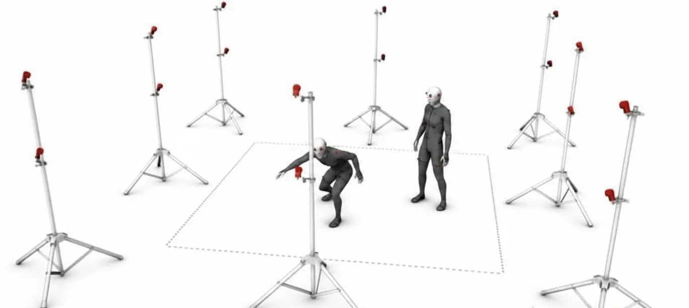
The Rift contains a number of infrared LEDs (the markers) that emit infrared light and are captured in real time by infrared cameras. After obtaining the infrared images, the camera data is sent to a compute unit where vision algorithms filter out irrelevant information to locate the directions of the infrared LEDs. Using a PnP algorithm and the known 3D positions of four non-coplanar LEDs on the device plus their image locations, the device can be placed into the camera coordinate system, fit a 3D model of the device, and track the user’s head and hand motion in real time.
The following sections describe the reasoning process and some algorithmic details.
LEDs on the headset
To use the four non-coplanar LEDs on the device for pose estimation, the system must be able to distinguish individual LEDs on the headset.
If LEDs are not distinguishable, then associating observed image points with predicted points during pose optimization becomes combinatorially expensive. For example:
- If there are N predicted image points and M observed image points with M <= N, there are N!/(N-M)! possible associations.
- For N = 40 and M = 20 (typical LED counts for DK2), that yields roughly 3.3e29 possible associations, which is computationally infeasible to resolve by brute force.
Clearly, DK2 must use some prior or structured method to distinguish light points. How does DK2 do this?
One hypothesis seen in some articles is that DK2 toggles LEDs on and off to encode identity. Although toggling is simple to detect, it is ambiguous because an LED might be occluded due to headset movement rather than being intentionally off. DK2 instead uses relative brightness information to distinguish LEDs. Consider grayscale camera captures:
Comparing the images shows that the apparent size and intensity of the light blobs change over time. For example, in some frames a given LED blob appears larger or brighter than in others. The actual implementation uses a differential method rather than directly measuring absolute blob size across frames. The following summarizes the inferred approach.
When capturing at roughly 60 Hz, patterns repeat every 10 frames. Label a few blobs by eye; for example, blob #2 might show a perceived brightness sequence like: weak, weak, strong, strong, weak, strong, weak, weak, weak, strong.
How is this brightness pattern represented internally?
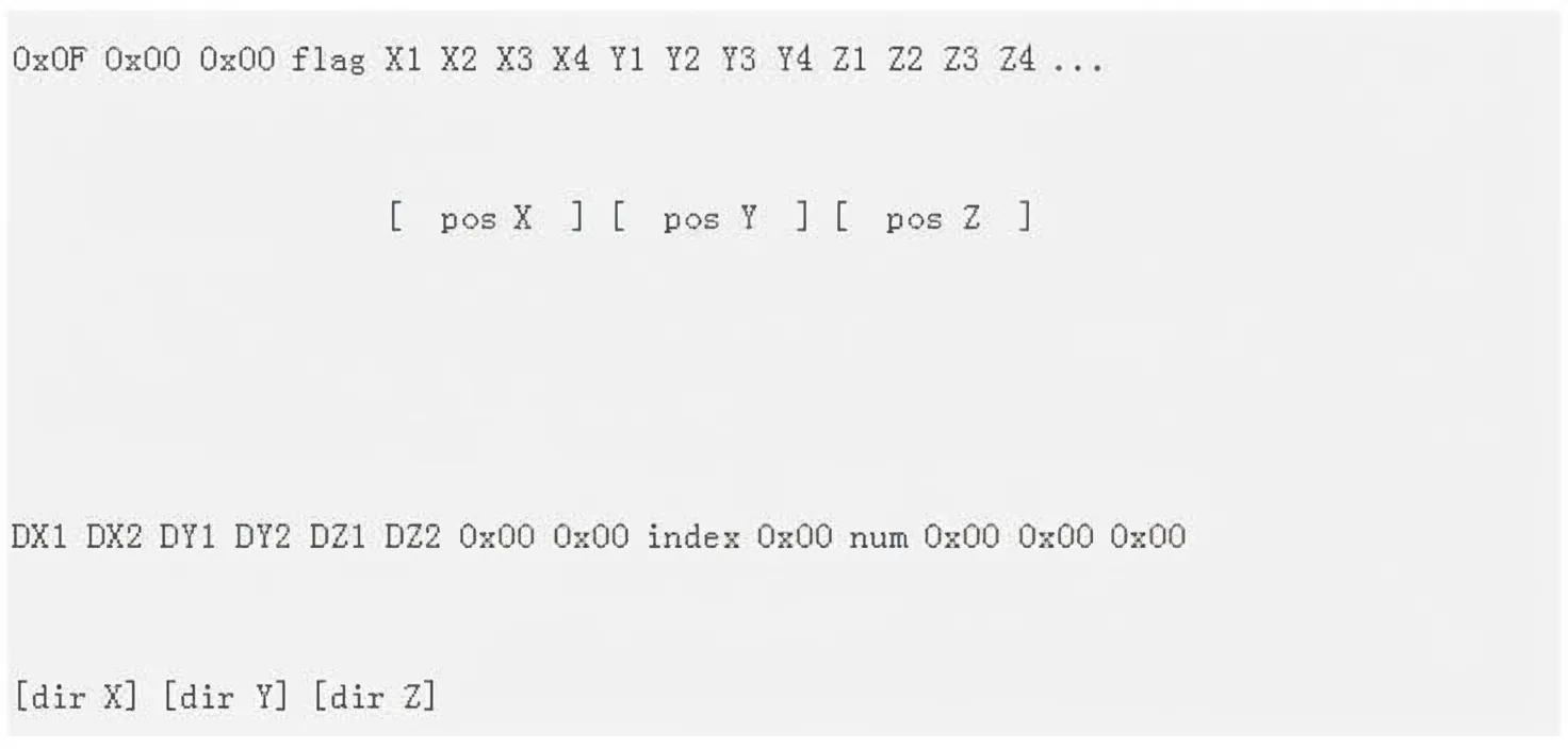
First, the SDK's Windows driver sends a start message to the headset to begin operation. After that, the driver continuously receives data messages such as an image showing values like:
X1 X2 X3 X4 are a 32-bit number representing spatial coordinates obtained after image analysis (the principle is explained later). The purpose of DX is unclear. Observing the num field yields a value of 40; index starts at 1 and increments up to 40, indicating DK2 enumerates LEDs one by one. These messages arrive approximately every 17 ms, similar to a 60 Hz capture rate, which suggests the system uses 10 frames per LED identification.
To confirm this, synchronization must be established.
If LED identity is encoded across 10-frame brightness variations, the camera and headset must be synchronized. A sync signal needs to be available to both the camera and the headset so that timing is known and the effective frequency can be determined.
Datasheet inspection of the MT9V034 camera shows a capture rate near 30 Hz. However, using differential detection, a 30 Hz camera can still capture brightness changes that are being encoded at a higher effective rate. In other words, DK2 does not simply classify blob size in isolation; it compares the current frame's blob with the same blob in the previous frame. If the blob is larger than the previous frame, it is classified as "large"; if smaller, "small". For each new frame, the algorithm extracts bright pixel blobs, discards blobs smaller than 10 pixels or not disk-shaped, and ensures extracted blobs correspond to large disk-shaped blobs from the previous frame before performing the comparison.
Therefore, DK2 determines LED IDs by comparing each blob to its previous-frame counterpart and using the pattern of large/small changes across 10 frames.
From analysis of point and position mapping, the DK2 rule for determining brightness change appears to be:
- If the current-frame blob is at least 10% larger than the previous-frame blob, record a 0.
- If the current-frame blob is at least 10% smaller than the previous-frame blob, record a 1.
- Otherwise, ignore the measurement.
This design is robust against random interference affecting LED brightness.