 ALLPCB


Introduction
Consumer demand for on-demand fitness metrics has created opportunities for applications that use heart rate monitors (HRM). HRMs are embedded not only in smartwatches and fitness wearables but also in exercise equipment. Among HRM approaches, pulse oximetry offers the greatest convenience for consumers. However, the electronic, mechanical, and software design requirements for pulse oximetry can add significant implementation complexity and delay to the final product.
Heart Rate Monitoring Requirements
Heart rate is one of the most familiar and easily measured indicators of exercise intensity. Health organizations express exercise intensity targets as a percentage of maximum heart rate, commonly estimated as 220 minus the individual?s age. The American Heart Association recommends most people begin an exercise program at about 50% of maximum intensity and not exceed about 85% of maximum.
Athletes and fitness enthusiasts use finer gradations of heart-rate intensity to target specific training conditions. Training above about 72–78% of maximum heart rate crosses from aerobic to anaerobic training. Exercise below this level provides central cardiovascular benefits such as improved cardiac output. Training above this threshold provides peripheral benefits such as improved capillarization.
At about 86–92% of maximum, training enters the onset of blood lactate accumulation (OBLA), where lactate accumulates to significant levels and performance declines. Training at OBLA improves an individual?s ability to clear lactate and enhances muscle performance for trained athletes.
Table 1: Athletes use heart-rate measurements to target specific training types (source: American College of Sports Medicine).
SpO2 and Additional Metrics
In addition to heart rate, training specialists track blood oxygen saturation to assess an individual?s oxygen utilization efficiency for greater insight than heart rate alone. SpO2 is the estimated oxygen saturation of hemoglobin measured by pulse oximetry and expressed as a percentage. SpO2 is a reasonable estimate of arterial oxygen saturation (SaO2), which is measured from a blood sample.
Pulse Oximetry
Heart-rate measurement leverages changes in light absorption associated with blood flow and hemoglobin oxygenation. A simple approach is photoplethysmography, which uses changes in skin light absorption as local blood volume increases briefly with each heartbeat. A more robust approach, pulse oximetry, uses the different light absorption properties of hemoglobin in oxygenated and deoxygenated states.
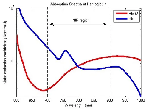
Deoxygenated hemoglobin (Hb) absorbs more red light than infrared, while oxygenated hemoglobin (HbO2) absorbs more infrared than red. Pulse oximeters compare absorption at about 660 nm (red) and about 880 nm (infrared) to compute SpO2. This differential measurement yields cleaner heart-rate data than simple photoplethysmography because it is less sensitive to motion, noise, and other artifacts. Although conceptually straightforward, implementing pulse oximetry involves several interesting challenges.
Design Challenges
Because the rate of blood-volume change is relatively low, typical pulse oximeter designs use correspondingly low acquisition rates. A typical approach alternates driving red and infrared LEDs at a low frequency and with minimal duty cycle to minimize power consumption. The low duty-cycle operation also allows baseline ambient-light measurements when both LEDs are off. When driving LEDs, designers must minimize noise while providing precise current pulses appropriate for each LED type. Careful timing control between red and infrared LED current pulses is also required to preserve measurement integrity. Designs that meet these constraints can become relatively complex.
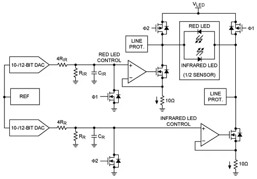
To drive each LED, designers sometimes use separate current-driver subcircuits, each including a digital-to-analog converter (DAC) for current control, a filter stage to reduce noise, and an operational amplifier in a transimpedance configuration. Each LED driver output is switched to its LED at the chosen frequency and duty cycle. The transimpedance amp configuration allows setting the required gain with minimal additional components. However, careful matching of components in each path is needed to minimize gain errors.
Variations on this architecture have their own trade-offs. For example, using a single DAC can reduce complexity but may increase noise. Higher output-side noise decreases the input-side signal-to-noise ratio (SNR) and reduces overall performance.
Pulse oximeter designers use two general approaches to measure red and infrared light. One approach performs most of the measurement in the analog domain with dedicated analog-to-digital converters (ADCs) for each wavelength or a single high-resolution ADC synchronized with the LED drivers. The alternative approach does much of the measurement in the digital domain, simplifying hardware at the cost of some software complexity. Both approaches rely on a transimpedance amplifier (TIA) to convert the photodiode output current to a voltage for ADC measurement.
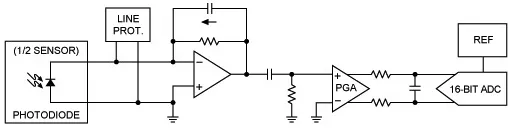
In pulse oximetry, the signal of interest generates relatively small photodiode currents compared with currents from ambient light. To maximize SNR in that environment, the TIA must exhibit very low input current and noise. High-pass filtering is often used to remove ambient-light components. A programmable gain amplifier (PGA) is typically set to use the ADC?s full dynamic range for optimal conversion resolution.
Beyond carefully designed LED outputs and photodiode input circuits, pulse oximeter design also requires proper mechanical placement of LEDs relative to the photodiode. Pulse oximeters use two physical configurations to measure transmitted or reflected light. Devices designed to clip onto a finger or earlobe measure transmission with the LED and photodiode on opposite sides, typically within opposite arms of a clip. LED light from one arm passes through the tissue and the photodiode in the other arm reads the transmitted level.
In contrast, wrist-worn devices or forehead sensors rely on reflection, where both LED and photodiode are on the same side making contact with the skin. Reflection-based HRMs offer greater placement flexibility since they can be positioned on any sufficiently flat skin area. However, designers must carefully position LED and photodiode relative to each other to optimize reception of red and infrared light reflected from subsurface blood flow.
Integrated Solutions
The differential measurement method used in pulse oximetry is simple in concept but conceals stringent analog and mechanical design requirements. Developers who want to add HRM capabilities to a product can avoid much of the mechanical and critical LED/photodiode circuit design by using an integrated biosensor module such as the Maxim Integrated MAX30102.
The MAX30102 is a self-contained module that addresses the electronic and mechanical requirements described above. In addition to low-noise LED current management and photodiode signal acquisition circuitry, it integrates red and infrared LEDs and a photodiode positioned for optimal optical measurement. Only a few external components are required to implement a pulse-oximetry subsystem that provides heart-rate data to a host processor.
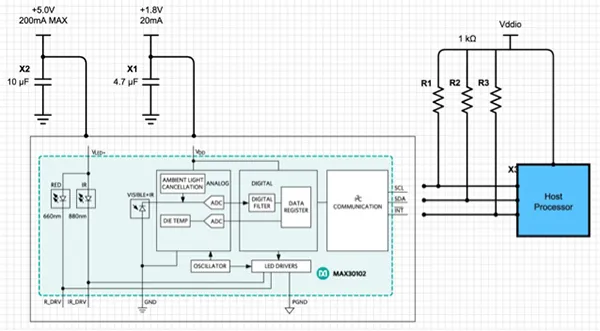
The module allows separate programming of the red and IR LED drive currents from 0 to 50 mA. LED pulse widths can be programmed from 69 μs to 411 μs to trade off measurement accuracy and power consumption. An integrated proximity function helps reduce power when the sensor is removed from the user?s skin.
On the input side, the device integrates a complete SpO2 measurement subsystem that combines ambient light cancellation (ALC), proprietary discrete-time filtering, and a sigma-delta ADC. The 18-bit ADC full-scale input range is programmable from 2 μA to 16 μA, and the sampling rate range spans 50 to 3,200 samples per second. An integrated temperature sensor enables temperature-related measurement compensation.
Measurement Process
The MAX30102 can operate as a traditional photoplethysmograph (PPG) in heart-rate mode using the red LED only, or in SpO2 mode using both red and IR LEDs. Heart-rate mode reduces power when the subject is stationary. During activity, motion artifacts can blur the pulse signal obtained with PPG. The SpO2 differential method provides more stable measurements during motion, though it requires correct sequencing of the two LEDs and increases power and operational complexity.
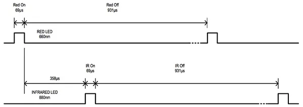
The MAX30102 supports alternating red and IR LED illumination sequences and provides separate LED channels. Each channel supports pulse durations of 69, 118, 215, or 411 μs, with preset time gaps between pulses of 358, 407, 505, or 696 μs respectively. The sampling rate implicitly limits the maximum pulse width. For example, at the maximum sample rate of 3,200 sps, the pulse width is limited to 69 μs, resulting in a 358 μs delay between the red and IR pulses. The selected pulse width also sets ADC resolution to 15 bits (69 μs), 16 bits (118 μs), 17 bits (215 μs), or 19 bits (411 μs).
The MAX30102 integrates a FIFO buffer that can store up to 32 samples, so the host processor does not need to read sensor output after every sample. The host can periodically read temperature data for compensation while relying on the FIFO to retain heart-rate samples as the MAX30102 continues sampling at the preset rate.
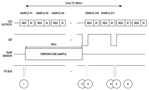
A complete SpO2 sampling sequence sets the device to SpO2 mode by writing 0x03 to bits 2:0 of the mode control register. During sampling, firmware can set TEMP_EN in the device temperature configuration register to start a temperature measurement. When the MAX30102 completes the temperature measurement it triggers the TEMP_RDY interrupt to notify the host, which clears the interrupt by reading the temperature. When the FIFO reaches the almost-full threshold, the device interrupts the host to read the FIFO, automatically clears the interrupt, and advances the FIFO read pointer to the next new sample. Because each FIFO read advances the FIFO pointer, this sequence can continue indefinitely until the application explicitly stops SpO2 measurements.
Quick Development
For developers seeking to accelerate HRM application development, Maxim Integrated provides the MAXREFDES117# reference design. The reference design includes hardware and software that together form a complete standalone HRM solution. The compact 12.7 mm x 12.7 mm board contains the MAX30102 heart-rate/SpO2 sensor, a low-power MAX1921 buck regulator, and a MAX14595 level translator.
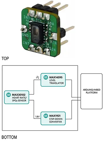
The MAX1921 buck regulator steps system power down to the 1.8 V required by the MAX30102. The MAX14595 level translator handles logic-level differences between the MAX30102 interface and the host board. The reference design board works with any MCU that provides an I2C interface. Maxim provides software library examples for ARM mbed and Arduino platforms.
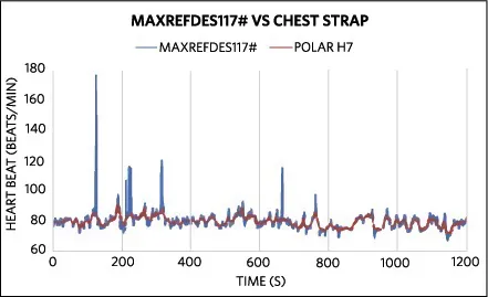
With sample software, the reference design board consumes less than 5.5 mW and achieves accuracy comparable to leading chest-strap HRM products.
Example Software
The example source code provides an HRM base library. The routine maxim_heart_rate_and_oxygen_saturation implements SpO2 algorithms and accepts the following inputs:
- aun_ir_buffer: pointer to IR sensor data buffer
- n_ir_buffer_length: IR sensor data buffer length
- aun_red_buffer: pointer to red sensor data buffer
The routine maxim_heart_rate_and_oxygen_saturation updates the following output parameters (provided as pointers in the function call):
- n_spo2: computed SpO2 value
- ch_spo2_valid: "1" if computed SpO2 is valid
- n_heart_rate: computed heart rate if valid
- ch_hr_valid: "1" if heart rate is valid
The sample code shows how an application collects five seconds of samples, then computes heart rate using maxim_heart_rate_and_oxygen_saturation, and continues sampling and computing until terminated by the user. Below is an extracted code fragment from the example. Chinese comments are translated to English; code symbols and formatting are preserved.
maxim_max30102_init();// Initialize MAX30102

n_brightness = 0;

un_min = 0x3FFFF;
un_max = 0;

n_ir_buffer_length = 500;// Buffer length 500 stores 5 seconds of samples at 100 sps

// Read first 500 samples and determine signal range
for(i = 0; i
{
    while(INT.read() == 1);// Wait until interrupt pin is set
    maxim_max30102_read_fifo((aun_red_buffer + i), (aun_ir_buffer + i)); // Read FIFO from MAX30102
    if(un_min > aun_red_buffer[i])
        un_min = aun_red_buffer[i];// Update signal min
    if(un_max
        un_max = aun_red_buffer[i];// Update signal max
}
un_prev_data = aun_red_buffer[i];
// Calculate heart rate and SpO2 after first 500 samples (first 5 seconds of samples)
maxim_heart_rate_and_oxygen_saturation(aun_ir_buffer, n_ir_buffer_length, aun_red_buffer, &n_sp02, &ch_spo2_valid, &n_heart_rate, &ch_hr_valid);

// Continuous sampling from MAX30102. Heart rate and SpO2 calculated every 1 second
while(1)
{
    // Loop forever, repeat the above sequence:
    // Read samples from FIFO
    // Calculate heart rate
}
Conclusion
Heart rate is an important metric for assessing personal health and fitness. Growing consumer interest in measuring this vital statistic makes heart-rate measurement an important differentiator in both fitness equipment and mainstream wearables. Pulse oximetry provides a flexible approach to heart-rate measurement but places stringent requirements on electronics, mechanics, and software. Integrated biosensor modules and reference designs can simplify implementation by providing tested LED, photodiode, and analog front-end functionality, along with example software, reducing the effort required to add pulse-oximetry capabilities to devices designed for fitness or everyday use.


