 ALLPCB


This article discusses harmonic current and voltage fluctuation/flicker, which are key measurements in electromagnetic interference (EMI) testing.
Harmonic Current
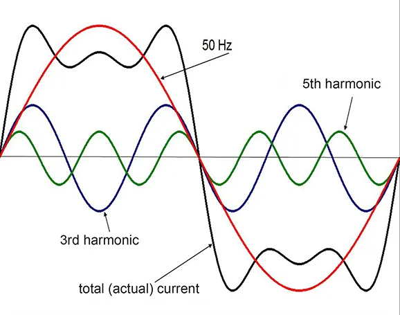
Harmonics are components of an electric current with frequencies that are integer multiples of the fundamental frequency. They are identified by performing a Fourier series decomposition on a periodic, non-sinusoidal waveform. In a broader sense, since the AC power grid operates at a single utility frequency, any component with a different frequency can be considered a harmonic.
Effects of Harmonic Current
Advances in semiconductor power conversion technology have significantly improved energy efficiency. However, the widespread use of switching power supplies and thyristors has also led to the generation of harmonic currents. These currents pose several serious risks:
- They increase the load on the grid's neutral conductor. Harmonic currents from numerous non-linear loads can flow through the neutral line, causing it to overload. In severe cases, this can burn out the conductor and create a fire hazard.
- They stress high-voltage capacitors on the power grid. Grid transformers often have high-voltage capacitors to filter high-frequency interference. High-frequency harmonic currents flowing through these capacitors can cause them to overheat and potentially explode.
- They can cause voltage waveform distortion on the grid, which affects the stable operation of other electrical products.
To protect the power quality of the public grid and ensure the normal operation of both the grid and user equipment, the International Electrotechnical Commission (IEC) has established standards for harmonic current limits. IEC 61000-3-2:2018, "Electromagnetic compatibility (EMC) - Part 3-2: Limits for harmonic current emissions (equipment input current ≤16 A per phase)," classifies equipment into four categories: A, B, C, and D.
Harmonic Current Test Standards
For low-voltage supply systems, the relevant product standards include:
- IEC 61000-3-2: For equipment with a rated current ≤ 16A.
- IEC 61000-3-4: For equipment with a rated current > 16A.
- IEC 61000-3-12: For equipment with a rated current > 16A and ≤ 75A.
Among the corresponding EN standards, only EN 61000-3-2 and EN 61000-3-12 are listed in the Official Journal of the European Union as harmonized EMC standards. Therefore, there is no harmonized standard for equipment with a rated current greater than 75A. The basic standard for test methods is IEC 61000-4-7.
Harmonic Current Test Method
- Equipment: A harmonic analyzer and a clean AC power source.
- Test Frequency Range: The test covers the 2nd to the 40th harmonic, which corresponds to a frequency range of 100 Hz to 2 kHz for a 50 Hz system.
- Harmonic Current Limit Standards: IEC 61000-3-2 specifies different limits based on the product's classification (Class A, B, C, or D).
Voltage Fluctuation and Flicker
Voltage Fluctuation
Voltage fluctuation and flicker tests measure the changes in mains voltage caused by the Equipment Under Test (EUT). The interference effect depends not only on the magnitude of the voltage change but also on its frequency of occurrence. Voltage changes are evaluated using two primary metrics: voltage fluctuation and flicker.
Voltage fluctuation refers to sudden, significant changes in the grid voltage. While it generally has a small impact on flicker measurement, it can significantly affect other electronic devices on the same grid.
Flicker measurement precisely assesses the effects of continuous voltage fluctuations. It quantifies the unstable visual perception caused by time-varying light stimuli, as perceived by the human eye.
Governing Standard: IEC 61000-3-3: "Limitation of voltage changes, voltage fluctuations and flicker in public low-voltage supply systems, for equipment with rated current ≤ 16 A per phase."
The relevant IEC standard specifies the following limits for relative voltage changes:
- The steady-state voltage change (dc) must not exceed 3.3%.
- The maximum voltage change (dmax) must not exceed 4%.
- The duration for which the voltage change (dt) exceeds 3.3% must be less than 500 ms.
Voltage Flicker
Flicker is measured in two ways:
- Short-term Flicker (Pst): This value assesses the flicker severity over a short period (10 minutes). A Pst of 1.0 is considered the threshold of irritability. Pst models the human perception of flicker from a 60W incandescent lamp on a 230V/50Hz supply during voltage fluctuations. The limit for Pst is 1.0.
- Long-term Flicker (Plt): This value assesses flicker severity over a longer period (2 hours), calculated from a sequence of 12 Pst values. The standard sets the limit for Plt at 0.65.


