ALLPCB


Overview
The EASY EAI Nano-TB is an AIoT mainboard based on the RV1126B processor. It integrates 1 MIPI DSI display interface, 2 MIPI CSI camera inputs, 2 Gigabit Ethernet ports, WiFi 6, a TF card slot, 2 USB 3.0 Type-A ports, 1 USB 2.0 Type-A port, audio input and output, and standard peripherals including SPI, SAI, PWM, I2C, UART, and a hardware watchdog. The board offers a rich set of interfaces, 3 Tops NPU performance, a quad-core CPU, strong codec capability, and a complete Linux development package for secondary development.
Key Features
- CPU: Quad core, 4x Cortex-A53 with NEON coprocessor
- Integrated NPU: Up to 3 Tops
- On-board storage: 1/2 GB DDR4, 64 GB eMMC
- Video input: 2x 4-lane MIPI CSI
- Video output: 1x MIPI DSI
- Ethernet: 2x Gigabit Ethernet
- WiFi / Bluetooth: WiFi 6 and Bluetooth 5.2
- SLE: SLE1.0 standard communication protocol
- Storage: 1x TF card slot
- USB: 2x USB 3.0, 1x USB 2.0
- Audio: 1x MIC input, 1x speaker output
- Peripherals: SPI, SAI, PWM, UART, I2C, GPIO, RTC, hardware watchdog
- Power: 12 V DC input
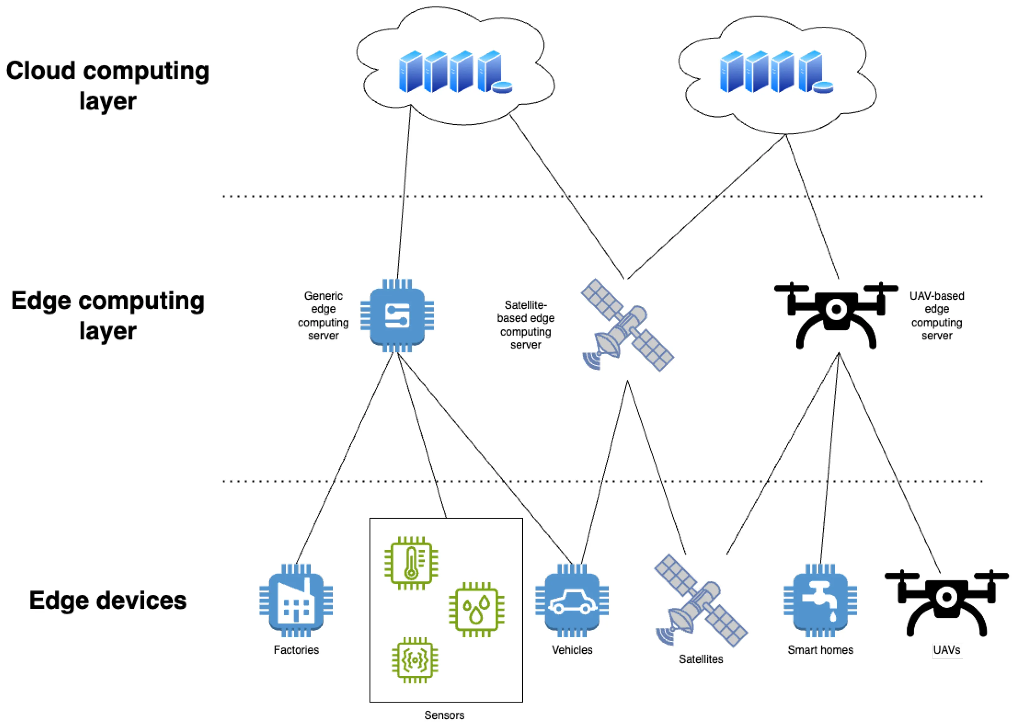
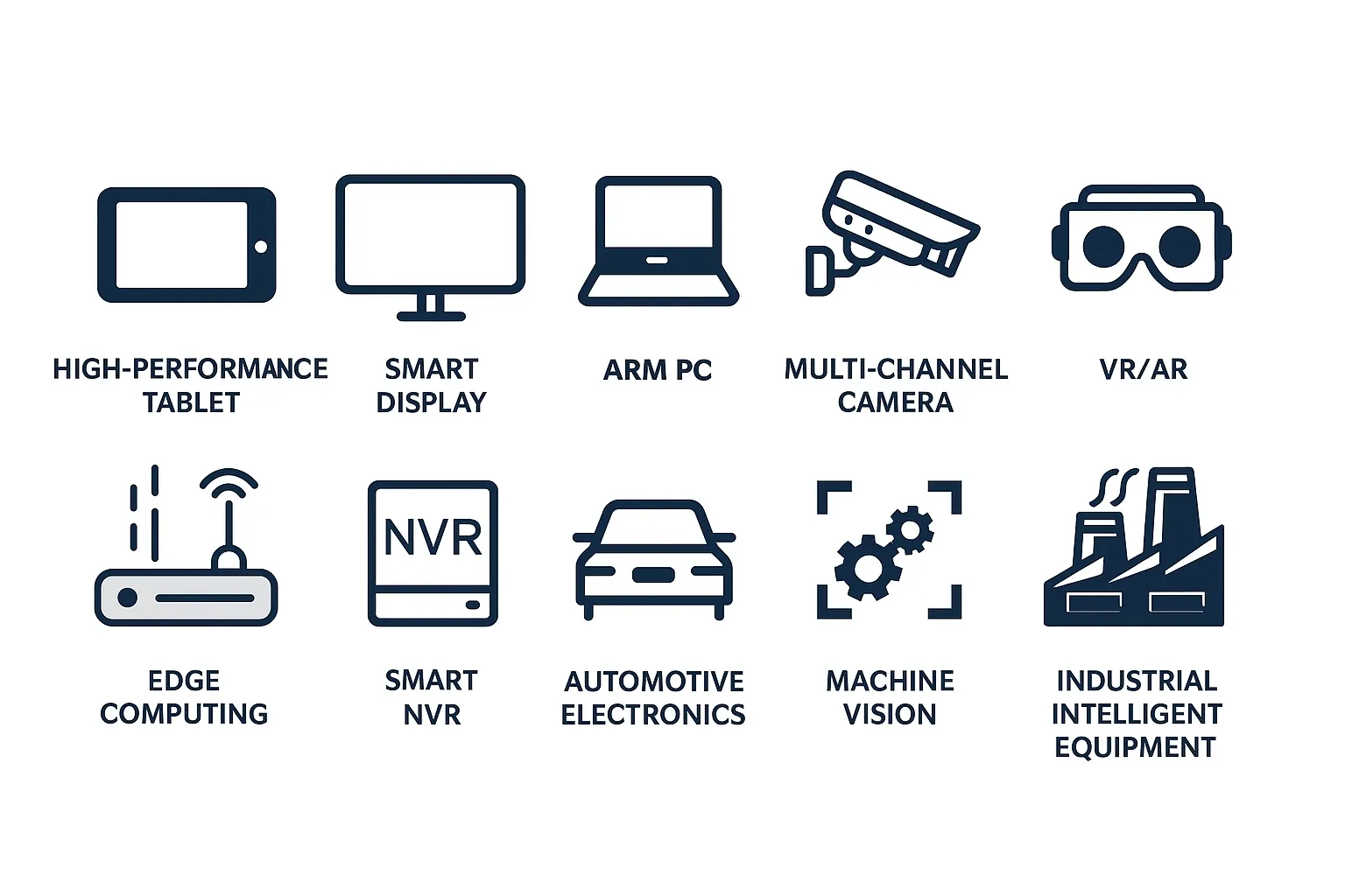
Typical Applications
Product Description
1.1 Product Overview
The EASY-EAI-Nano-TB core board is designed for AIoT applications using the Rockchip RV1126B processor. It integrates 4 Cortex-A53 cores and an independent NEON coprocessor, supports 4K@30fps H.264/H.265 decoding and encoding, and includes a generation of hardware ISP up to 12 MP. The ISP provides acceleration for features such as HDR, 3A, LSC, 3DNR, 2DNR, sharpening, dehaze, fisheye correction, gamma correction, and feature point detection. An 8 MP AI-ISP is included as a complement to the traditional ISP, improving spatial noise reduction and image enhancement. The embedded NPU delivers up to 3 Tops and supports mixed precision INT4/INT8/INT16/FP16. A complete Linux development package is provided for secondary development.
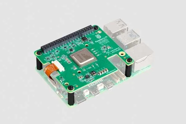
1.2 Product Images
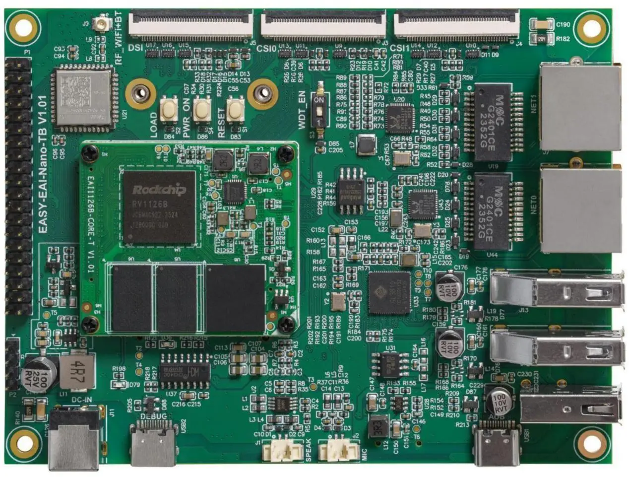
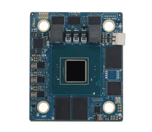
Product front view
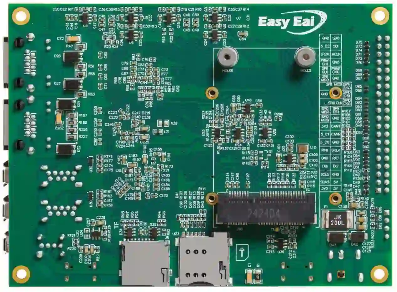
Product rear view
1.3 Specifications
| Name | EASY EAI Nano-TB |
|---|---|
| Processor | RV1126B |
| Cores | 4× ARM Cortex-A53 @ 1.6 GHz |
| NPU | Supports INT4/INT8/INT16/FP16 mixed precision, up to 3 Tops |
| VPU | 4K@30fps H.264/H.265 Decoder and 4K@30fps H.264/H.265 Encoder |
| ISP | 12 MP ISP + 8 MP AI-ISP |
| OS | Debian 12 / Ubuntu 22.04 |
| Memory | 1/2 GB LPDDR4X |
| Storage | 64 GB eMMC |
| MIPI DSI | 1x 4-lane MIPI DSI, 1.5 Gbps/lane |
| MIPI CSI | 2x, each supports 4 lanes, 2.5 Gbps/lane |
| TF Card | 1x TF card slot |
| USB 3.0 Host | 2x USB 3.0 Type-A |
| USB 2.0 Host | 1x USB 2.0 Type-A |
| Type-C | 1x firmware download interface |
| Ethernet | 2x Gigabit Ethernet |
| WiFi | WiFi 6 |
| Bluetooth | Bluetooth 5.2 |
| SLE | SLE1.0 communication |
| Microphone | 1x microphone input |
| Speaker | 1x 3 W / 4 Ω speaker output |
| UART | 2x, 3.3 V |
| CAN | 1x, 3.3 V |
| I2C | 1x |
| PWM | 2x |
| SPI | 2x |
| SAI | 1x |
| GPIO | 3x |
| Debug UART | 1x |
| LED | 1x power indicator |
| Buttons | 1x reset, 1x LOAD, 1x PWRON |
| Watchdog | External hardware watchdog supported |
| Power input | 12 V DC |
| Mechanical size | 120 mm × 90 mm |
| Operating temperature | -20°C to +85°C |
2. Resources
2.1 RV1126B Processor
The RV1126B integrates 4 Cortex-A53 cores and an independent NEON coprocessor, supports 4K@30fps H.264/H.265 decoding and encoding, and includes a 3D GPU with compatibility for OpenGL ES 1.1/2.0/3.2, OpenCL 2.2, and Vulkan 1.2. The embedded NPU supports INT4/INT8/INT16/FP16 mixed precision up to 3 Tops. Models from frameworks such as TensorFlow, MXNet, PyTorch, and Caffe can be converted for deployment.
2.2 Display Interface
The board integrates 1x 4-lane MIPI DSI output.
2.2.1 MIPI DSI
The board includes 1 MIPI DSI supporting D-PHY v2.0, up to 1.5 Gbps/lane. Maximum supported resolution is 1920×1080@60 Hz, supporting RGB up to 24 bits. The physical connector is a 40-pin, 0.5 mm pitch horizontal FPC socket. The MIPI DSI connector is labeled J5.

2.3 Image Input Interfaces
The board provides 2 MIPI CSI interfaces for dual HD video input. The processor supports 4K@30fps H.264 and H.265 encoding.
2.3.1 MIPI CSI
Two MIPI CSI interfaces are integrated, supporting D-PHY v1.2. Each interface is 4 lanes and supports up to 2.5 Gbps/lane. The physical connector is a 40-pin, 0.5 mm pitch horizontal FPC socket. Signal definitions for both interfaces are the same. The two MIPI CSI connectors are silk-screened as "MIPI CSI0" (J3) and "MIPI CSI1" (J4).

2.4 TF Card Slot
The board includes 1 TF card slot for data storage, labeled J8. It supports SDIO 3.0 and dynamic signal voltage selection for 1.8 V and 3.3 V. The TF card can be used as a system boot device and supports TF card boot.
2.5 USB
The board provides 2 USB 3.0 ports, 1 USB 2.0 port, and 1 Type-C port used for firmware download.
2.5.1 USB 3.0
There are 2 USB 3.0 Type-A ports provided via a USB 3.0 hub IC. These are full-function USB 3.0 ports that include USB 2.0 signals. The physical connectors are Type-A, labeled J12 and J13.
2.5.2 USB 2.0
One USB 2.0 Type-A port is available and supports HS/FS/LS modes. It shares USB signals with the Type-C connector, so only one of the two can be used at a time. The Type-A connector is labeled USB3.
2.5.3 Type-C
One USB 2.0 Type-C connector is provided for system firmware download. It is labeled USB1.
2.6 Ethernet
The board integrates 2 Gigabit Ethernet ports with auto-negotiation for 10/100/1000 Mbps. RJ45 connectors are used. LAN0 is labeled J7 and LAN1 is labeled J6.
2.7 WiFi, Bluetooth, and SLE
The board integrates a DB37 tri-mode wireless module supporting IEEE 802.11 b/g/n/ax @ 2.4 GHz, BLE 5.2, and the SLE1.0 protocol. It supports SDIO 2.0 and 802.11n 20/40 MHz and 802.11ax 20 MHz bandwidths, offering up to 150 Mbps physical layer rate and extended coverage. The module has an antenna connector using an IPX socket, labeled U21. WiFi and Bluetooth characteristics are shown below.
| Name | Feature | Description |
|---|---|---|
| 2.4 GHz WiFi | WiFi standard | IEEE 802.11 b/g/n & Wi-Fi compliant |
| Frequency range | 2.400 GHz to 2.4835 GHz (2.4 GHz ISM band) | |
| Channels | 2.4 GHz: Ch1 to Ch13 | |
| Modulation | 802.11b: DQPSK, DBPSK, CCK; 802.11g/n: OFDM (64-QAM, 16-QAM, QPSK, BPSK); 802.11ax: OFDM (256-QAM, 64-QAM, 16-QAM, QPSK, BPSK) | |
| Bluetooth | Bluetooth standard | BLE 5.2 |
| Frequency range | 2400 MHz to 2483.5 MHz (2.4 GHz ISM band) | |
| Channels | LE: Ch0 to Ch39 | |
| Modulation | GFSK | |
| SLE | SLE standard | SLE1.0 |
| Operating frequency | 2400 MHz to 2483.5 MHz (2.4 GHz ISM band) | |
| Modulation | GFSK, BPSK, QPSK |
2.8 Audio
The board supports one microphone input and one speaker output.
2.9 Mini PCIe Expansion
One mini PCIe expansion connector is provided, labeled J10. It exposes USB 2.0 signals only and does not support PCIe lanes. It can be used for USB-based 4G modules or other USB expansion modules.
2.10 Single-row Header
The board includes a single-row header providing ADC and UART signals. The connector pitch is 2.54 mm and is labeled P2. Pin descriptions are listed below.
| Pin | Signal | Description |
|---|---|---|
| 1 | ADC0_IN2 | ADC0 channel 2 |
| 2 | UART2_RX_M0 | UART2 RX (3.3 V) |
| 3 | UART2_TX_M0 | UART2 TX (3.3 V) |
| 4 | GND | Ground |
2.11 Expansion Header
An expansion header is provided with ADC, I2C, UART, and other signals. The connector pitch is 2.54 mm and is labeled P1. Pin descriptions are listed below.
| Pin | Signal | Description |
|---|---|---|
| 1 | VCC_3V3 | 3.3 V output |
| 2 | VCC_5V | 5 V output |
| 3 | I2C5_SDA_M0 | I2C5 SDA (3.3 V) |
| 4 | VCC_5V | 5 V output |
| 5 | I2C5_SCL_M0 | I2C5 SCL (3.3 V) |
| 6 | GND | Ground |
| 7 | UART6_TX_M0 | UART6 TX (3.3 V) |
| 8 | UART7_TX_M0 | UART7 TX (3.3 V) |
| 9 | GND | Ground |
| 10 | UART7_RX_M0 | UART7 RX (3.3 V) |
| 11 | UART6_RX_M0 | UART6 RX (3.3 V) |
| 12 | SAI1_SCLK_M2 | SAI1 serial clock (3.3 V) |
| 13 | GPIO5_C0_D | GPIO5_C0_D (3.3 V) |
| 14 | GND | Ground |
| 15 | GPIO5_C1_D | GPIO5_C1_D (3.3 V) |
| 16 | CAN0_RXD_M1 | CAN RX (3.3 V) |
| 17 | VCC_3V3 | 3.3 V output |
| 18 | CAN0_TXD_M1 | CAN TX (3.3 V) |
| 19 | SPI0_MOSI_M2 | SPI0 MOSI (3.3 V) |
| 20 | GND | Ground |
| 21 | SPI0_MISO_M2 | SPI0 MISO (3.3 V) |
| 22 | SPI1_CSN1_M1 | SPI1 CS1 (3.3 V) |
| 23 | SPI0_CLK_M2 | SPI0 CLK (3.3 V) |
| 24 | SPI0_CSN0_M2 | SPI0 CS0 (3.3 V) |
| 25 | GND | Ground |
| 26 | SPI0_CSN1_M0 | SPI0 CS1 (3.3 V) |
| 27 | SPI1_MOSI_M1 | SPI1 MOSI (3.3 V) |
| 28 | SPI1_CSN0_M1 | SPI1 CS0 (3.3 V) |
| 29 | SPI1_MISO_M1 | SPI1 MISO (3.3 V) |
| 30 | GND | Ground |
| 31 | SPI1_CLK_M1 | SPI1 CLK (3.3 V) |
| 32 | PWM1_CH0_M1 | PWM1 channel 0 output (3.3 V) |
| 33 | PWM1_CH1_M1 | PWM1 channel 1 output (3.3 V) |
| 34 | GND | Ground |
| 35 | SAI1_LRCK_M2 | SAI1 frame clock (3.3 V) |
| 36 | SAI1_MCLK_M2 | SAI1 master clock (3.3 V) |
| 37 | GPIO5_C2_D | GPIO5_C2_D (3.3 V) |
| 38 | SAI1_SDI_M2 | SAI1 data input |
| 39 | GND | Ground |
| 40 | SAI1_SDO_M2 | SAI1 data output |
2.12 LEDs
Two surface-mount LEDs are provided. D79 is the power indicator, and D36 indicates 4G module communication status.
2.13 Buttons
Three tactile buttons are integrated. Descriptions are:
| Location | Name | Description |
|---|---|---|
| S1 | RESET | Reset button |
| S2 | LOAD | Loader mode button. Hold this button and press RESET to enter loader download mode. |
| S4 | PWRON | Power on/off button |
2.14 Hardware Watchdog
An external hardware watchdog is integrated. The watchdog timeout interval is 1.6 s. If not fed within 1.6 s, the watchdog will generate a reset signal. The default system feeds the watchdog every 0.8 s. The watchdog can be enabled or disabled via the S3 DIP switch: set the "WDT" position to "ON" or "1" for normal operation.
2.15 DC Jack
The power input is a 5.5 mm standard DC jack labeled J11. The required supply is 12 V DC. A 12 V, 3 A adapter is recommended.
3. Electrical Parameters
3.1 Power Parameters
| Condition | Voltage | Current | Power | Unit |
|---|---|---|---|---|
| System normal boot | 12 V | 0.195 A | 2.34 W | V / A / W |
| Freeze sleep mode | 12 V | 0.069 A | 0.828 W | V / A / W |
| Mem sleep mode | 12 V | 0.083 A | 0.996 W | V / A / W |
| CPU 50% load (2 cores) | 12 V | 0.225 A | 2.70 W | V / A / W |
| CPU 100% load (4 cores) | 12 V | 0.255 A | 3.06 W | V / A / W |
| CPU 50% + NPU full load | 12 V | 0.393 A | 4.71 W | V / A / W |
4. Mechanical Dimensions
| Parameter | Value | Notes |
|---|---|---|
| Board length | 120 mm | |
| Board width | 90 mm | |
| Mounting hole size | 3 mm | Use M3 screws for mounting |
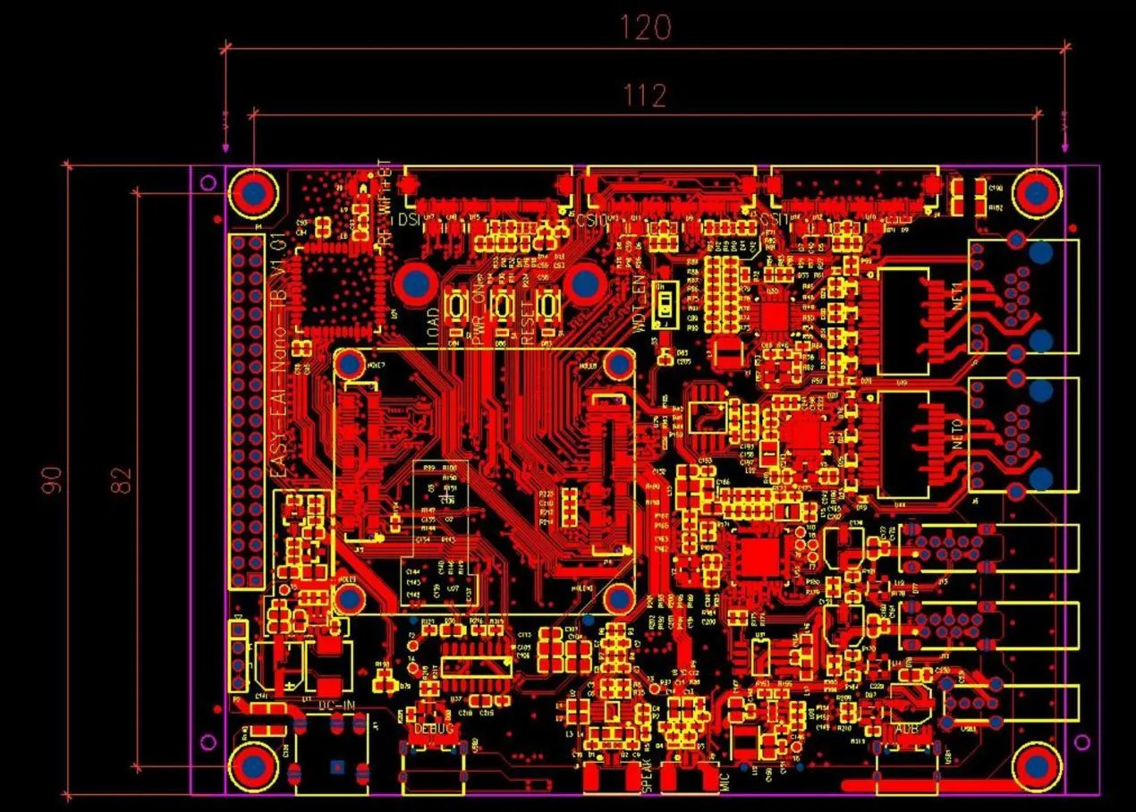
Mechanical dimensions
5. Disclaimer
The information in this manual is provided to the best of the manufacturer's knowledge. Content may change over time. The manufacturer reserves the right to update the manual without prior notice. Users should refer to the latest official documentation for up-to-date information.