ALLPCB


What is DMA
DMA, Direct Memory Access, provides direct data transfers between peripherals and memory or between memory regions without continuous CPU involvement.
DMA transfers move data from one address space to another, enabling high-speed transfers between peripherals and memory or between two memory regions.
The CPU handles many tasks including data movement, computation, and control flow. Data copying and storage can consume significant CPU cycles. Offloading large or repetitive data transfers to DMA frees CPU resources for computation and control tasks.
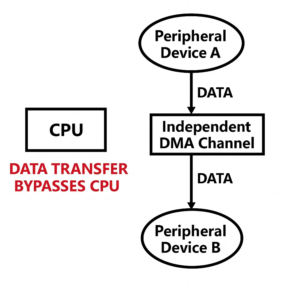
For example, to copy data from peripheral A to peripheral B, provide a data path between the two peripherals so data can move directly from A to B without CPU mediation.
DMA Purpose
DMA addresses the problem of excessive CPU usage caused by large data transfers. With DMA, the CPU can focus on computation and control while DMA handles bulk data movement.
Definition
DMA provides high-speed data transfers between peripherals and memory or between memory regions without CPU intervention, saving CPU resources for other tasks.
DMA Transfer Types
DMA enables direct transfers without passing data through CPU registers. The four transfer scenarios are essentially the same: moving data from one memory area to another. Peripheral data registers are treated as memory cells. The cases are:
- Peripheral to memory
- Memory to peripheral
- Memory to memory
- Peripheral to peripheral
DMA Transfer Parameters
Key DMA parameters are: source address, destination address, transfer size, and transfer mode. After the user configures source, destination, and transfer size, the DMA controller starts the transfer. When the remaining transfer count reaches zero, the transfer ends. DMA can also run in circular mode so that when the end is reached it reloads and restarts the transfer. As long as the transfer count is not zero and DMA is enabled, transfers occur.
Main DMA Features
- Each channel connects to dedicated hardware DMA requests and also supports software triggering. These features are configured in software.
- Multiple requests on the same DMA module have programmable priorities (four levels: very high, high, medium, low). If priorities are equal, hardware decides (lower request number has higher priority).
- Independent source and destination transfer widths (byte, halfword, word) support packing and unpacking. Source and destination addresses must be aligned to the transfer width.
- Support for circular buffer management.
- Each channel has three event flags (half-transfer, transfer-complete, transfer-error); these flags can be ORed into a single interrupt request.
- Support for memory-to-memory, peripheral-to-memory, and memory-to-peripheral transfers.
- Flash, SRAM, peripheral SRAM, APB1, APB2, and AHB peripherals can be used as transfer sources or destinations.
- Programmable transfer count up to 65535.
STM32 DMA Resources
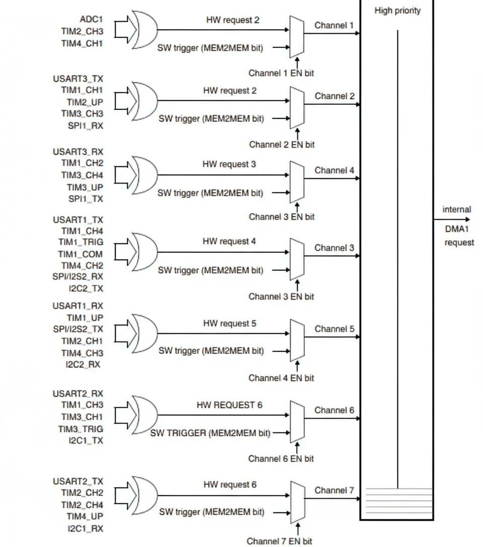
High-capacity STM32 devices provide two DMA controllers. DMA1 has seven channels and DMA2 has five channels. Each channel maps to specific peripherals.
DMA1 controller
Seven DMA requests from peripherals such as TIMx, ADC1, SPI1, SPI/I2S2, I2C1/2, and USART1/2/3 are input to DMA1. Each channel corresponds to specific peripherals.
DMA2 controller
Five DMA requests from peripherals such as TIM5/6/7/8, ADC3, SPI/I2S3, UART4, DAC channels 1 and 2, and SDIO are input to DMA2. Each channel corresponds to specific peripherals.
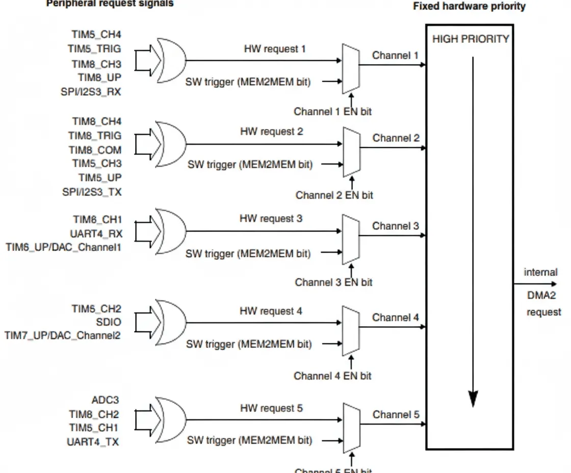
These mappings are visible in the system block diagram below.
DMA System Block
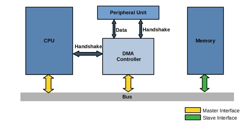
The block contains the CPU core, memory, peripherals, and DMA connections. Hardware components connect via the bus matrix. Data transfers among these components are coordinated by the bus matrix to allow peripherals to share the bus. The following sections analyze how ADC-acquired data is stored to SRAM with and without DMA.
Without DMA
Without DMA, the CPU acts as the intermediary. To move ADC data to SRAM:
- The core accesses the peripheral ADC data via the DCode bus and the bus matrix.
- The core then writes the data through the bus matrix to SRAM.
With DMA
With DMA:
- The peripheral issues a DMA request.
- The DMA controller receives the request and starts the transfer.
- The DMA controller reads ADC data from the AHB peripheral and stores it in the DMA channel.
- The DMA controller coordinates with the bus matrix and uses the AHB to write ADC data from the DMA channel into SRAM. This transfer occurs without CPU involvement.
More technically: after an event, the peripheral sends a request to the DMA controller. The DMA controller handles requests according to channel priority. When the DMA controller starts accessing the peripheral, it sends an acknowledge signal. Once the peripheral receives the acknowledge, it releases its request. After the DMA completes servicing the peripheral, the acknowledge is withdrawn. If more requests are pending, the peripheral can initiate the next cycle.
Each DMA transfer consists of three operations:
- Read data from the peripheral data register or from the memory address indicated by the current peripheral/memory address register. The start address for the first transfer is the peripheral or memory base specified in DMA_CPARx or DMA_CMARx.
- Write data to the peripheral data register or the memory address indicated by the current peripheral/memory address register. The start address for the first transfer is the peripheral or memory base specified in DMA_CPARx or DMA_CMARx.
- Decrement the DMA_CNDTRx register, which holds the number of remaining data items.
DMA Transfer Modes
Method 1: DMA_Mode_Normal. The transfer stops after a single transfer sequence.
Method 2: DMA_Mode_Circular. When the transfer completes, the hardware reloads the transfer count and starts the next cycle, enabling repeated transfers.
Arbiter
The arbiter determines DMA transfer priorities. Priority management has two stages:
Software: each channel's priority is set in the DMA_CCRx register. There are four levels: very high, high, medium, low.
Hardware: if two requests share the same software priority, the channel with the lower channel number has higher hardware priority. For example, with equal software priority, channel 2 has priority over channel 4.
Note: On high-capacity products, DMA1 has higher priority than DMA2.
DMA Stream Mapping (STM32F4/M4)
After selecting a DMA channel, select the peripheral data stream mapped to that channel.
Each DMA controller stream provides a unidirectional link between source and destination. Streams support:
- normal transactions: memory-to-peripheral, peripheral-to-memory, or memory-to-memory
- double-buffer transactions: using two memory pointers so the application can access one buffer while DMA operates on the other
Transfer size up to 65535 is programmable and is related to the source width of the peripheral on the connected AHB port. After each transaction, the register holding the remaining number of data items decrements.
DMA_SxCR selects which channel a stream uses. Each stream can choose one of 8 channels. Only one channel is active per stream at a time.
DMA Channels and Transfer Count
Each channel can perform DMA transfers between fixed peripheral addresses and memory addresses. The transfer count is programmable up to 65535 and the count register decrements during transfers. Transfer widths for peripheral and memory are programmable via PSIZE and MSIZE bits in the DMA_CCRx register.
Pointer Increment Mode
Peripheral and memory pointers can be incremented or kept constant after each transfer depending on the PINC and MINC bits in DMA_SxCR. In increment mode, the next address equals the previous address plus the increment value.
Increment mode is useful to access sequential memory. If enabled, the increment equals 1, 2, or 4 data widths according to PSIZE and MSIZE settings.
Memory-to-Memory Mode
DMA channels can operate without peripheral requests in memory-to-memory mode. When MEM2MEM bit in DMA_CCRx is set and the EN bit is set, the DMA channel starts transferring. The transfer ends when DMA_CNDTRx reaches 0. Memory-to-memory mode cannot be used with circular mode.
Note: only DMA2 peripheral interface can access memory for memory-to-memory transfers, so only DMA2 supports memory-to-memory mode. DMA1 does not support it.
DMA Interrupts
Each DMA channel can generate interrupts for half-transfer, transfer-complete, and transfer-error. These interrupts are enabled by setting bits in the appropriate registers. Even if interrupts are not enabled, these status bits can be polled to determine transfer state. A common flag used is TCIFx, the transfer-complete flag for stream x.
When PSIZE and MSIZE differ, the DMA aligns data according to the configured widths.
Note: On high-capacity devices, DMA2 channel 4 and DMA2 channel 5 share the same interrupt vector. On connectivity-line devices, DMA2 channel 4 and DMA2 channel 5 have separate interrupt vectors. All other DMA channels have individual interrupt vectors.
DMA and System Bus Usage
STM32 controllers use a Cortex-M core with an optimized bus structure. DMA uses a separate bus interface and does not conflict with the CPU system bus in normal operation. DMA use does not inherently slow the CPU.
However, the DMA controller and the CPU share the system data bus to perform direct memory transfers. When CPU and DMA concurrently access the same target (RAM or peripheral), DMA requests may stall CPU access to the system bus for several cycles. The bus arbiter schedules access to guarantee the CPU at least half of the system bus bandwidth for memory or peripheral access.
DMA Configuration
This section covers DMA registers and the DMA library API.
DMA Registers
Configuration parameters include channel addresses, priority, transfer direction, peripheral/memory data widths, address increment mode, circular mode, and transfer count.
DMA interrupt status register (DMA_ISR)
If DMA interrupts are enabled, the CPU jumps to the interrupt handler when conditions are met. If interrupts are not enabled, these bits can still be polled. The TCIFx bit indicates whether the channel transfer is complete. DMA_ISR is read-only, so flags must be cleared through other registers.
DMA interrupt flag clear register (DMA_IFCR)
Bits in DMA_IFCR clear the corresponding bits in DMA_ISR. Write 0 to clear the ISR bits. After a DMA_ISR bit is set, clear it by writing the appropriate bits in DMA_IFCR.
DMA channel configuration register (DMA_CCRx)
This register controls DMA settings including data width, peripheral and memory widths, channel priority, increment modes, transfer direction, interrupt enables, and enable. DMA_CCRx is the core control register for a DMA transfer.
DMA channel transfer count register (DMA_CNDTRx)
DMA_CNDTRx sets the number of data items to transfer for channel x. Range is 0 to 65535. This register decrements during transfer and reaches 0 when the transfer completes. It can be used to monitor transfer progress.
DMA peripheral address register (DMA_CPARx)
This register holds peripheral addresses. For example, using UART1 requires writing 0x40013804 (that is, &USART1_DR) into this register. For other peripherals, write the appropriate peripheral data register address.
DMA memory address register (DMA_CMARx)
Similar to DMA_CPARx, DMA_CMARx holds the memory address. For example, to use a SendBuf[5200] array, write &SendBuff into DMA_CMARx.
DMA Channel Configuration Procedure
- Set the peripheral address in DMA_CPARx. This address is the source or destination for peripheral transfers.
- Set the memory address in DMA_CMARx. The transfer will read from or write to this address.
- Set the transfer count in DMA_CNDTRx. This value decrements after each transfer.
- Set channel priority in DMA_CCRx PL[1:0] bits.
- Configure transfer direction, circular mode, peripheral/memory increment modes, data widths, and interrupt enables in DMA_CCRx.
- Set the ENABLE bit in DMA_CCRx to start the channel.
Once enabled, the DMA channel responds to connected peripheral requests. When half the data is transferred, the half-transfer flag (HTIF) is set and a half-transfer interrupt can be generated if enabled. At transfer end the transfer-complete flag (TCIF) is set and a transfer-complete interrupt can be generated if enabled.
DMA Library Functions
1. DMA initialization and deinitialization
DMA_DeInit(DMAX_ChannelX);
Resets DMAyChannelx registers to their default values.
Note: RCC_ResetCmd does not define DMA reset, so DMA registers are manipulated directly.
void DMA_Init(DMA_Channel_TypeDef* DMAy_Channelx, DMA_InitTypeDef* DMA_InitStruct)
Sets channel parameters including peripheral base address, memory base address, transfer count, increment modes, data widths, mode, priority, and memory-to-memory mode.
Structure example:
typedef struct {
uint32_t DMA_PeripheralBaseAddr;
/* Set DMA source address */
uint32_t DMA_MemoryBaseAddr;
/* Set DMA destination address */
uint32_t DMA_DIR;
/* Set transfer direction, determining whether data is read from peripheral to memory or from memory to peripheral */
uint32_t DMA_BufferSize;
/* Set transfer size */
uint32_t DMA_PeripheralInc;
/* Set whether peripheral address increments */
uint32_t DMA_MemoryInc;
/* Set whether memory address increments during transfer */
uint32_t DMA_PeripheralDataSize;
/* Peripheral data width: byte(8bits), halfword(16bits), or word(32bits) */
uint32_t DMA_MemoryDataSize;
/* Memory data width */
uint32_t DMA_Mode;
/* DMA mode: normal or circular */
uint32_t DMA_Priority;
/* DMA channel priority: low, medium, high, very high */
uint32_t DMA_M2M;
/* Set whether memory-to-memory mode is enabled */
} DMA_InitTypeDef;
2. DMA enable/disable
void DMA_Cmd(DMA_Channel_TypeDef* DMAy_Channelx, FunctionalState NewState);
Enable or disable a DMA channel. Example: DMA_Cmd(DMA1_Channel1, ENABLE);
3. DMA interrupt configuration
void DMA_ITConfig(DMA_Channel_TypeDef* DMAy_Channelx, uint32_t DMA_IT, FunctionalState NewState);
Configure DMA channel interrupts. DMA_IT_TC: transfer complete; DMA_IT_HT: half transfer; DMA_IT_TE: transfer error. Example: DMA_ITConfig(DMA1_Channel1, DMA_IT_TC, ENABLE);
4. Set and get current data counter (channel transfer count)
void DMA_SetCurrDataCounter(DMA_Channel_TypeDef* DMAy_Channelx, uint16_t DataNumber);
uint16_t DMA_GetCurrDataCounter(DMA_Channel_TypeDef* DMAy_Channelx);
The first function sets the transfer count (DMA must be disabled). The second retrieves the remaining transfer count (DMA enabled).
DMA Library Configuration Steps
- Enable DMA clock: RCC_AHBPeriphClockCmd();
- Initialize DMA channel: DMA_Init(); // set channel, addresses, direction, count, widths, mode, priority, M2M flag
- Enable peripheral DMA requests. For UART, call USART_DMACmd().
- Enable the DMA channel: DMA_Cmd();
- Check DMA transfer status: DMA_GetFlagStatus();
- Get current remaining data count: DMA_GetCurrDataCounter(DMA1_Channel4);
UART and DMA
DMA acts as a data mover. For UART receive without DMA, a UART interrupt triggers the CPU to read the UART data register and store data to memory. With DMA, the DMA engine moves the UART data register contents into memory upon interrupt, reducing CPU involvement. The CPU only needs to inspect memory.
Example DMA Configuration Code
1) DMA initialization
void dma_init()
{
 DMA_InitTypeDef DMA_InitStructure;
 RCC_AHBPeriphClockCmd(RCC_AHBPeriph_DMA1,ENABLE);
 /* DMA configuration */
 DMA_InitStructure.DMA_PeripheralBaseAddr = USART1_DR_Base;// UART data register address
 DMA_InitStructure.DMA_MemoryBaseAddr = (uint32_t)SendBuff; // memory address (pointer to data)
 DMA_InitStructure.DMA_DIR = DMA_DIR_PeripheralDST; // direction (memory to peripheral)
 DMA_InitStructure.DMA_BufferSize = 500; // transfer size
 DMA_InitStructure.DMA_PeripheralInc = DMA_PeripheralInc_Disable; // peripheral address no increment
 DMA_InitStructure.DMA_MemoryInc = DMA_MemoryInc_Enable; // memory address increments
 DMA_InitStructure.DMA_PeripheralDataSize = DMA_PeripheralDataSize_Byte ; // peripheral data unit
 DMA_InitStructure.DMA_MemoryDataSize = DMA_MemoryDataSize_Byte ; // memory data unit
 DMA_InitStructure.DMA_Mode = DMA_Mode_Normal ; // DMA mode: normal/circular
 DMA_InitStructure.DMA_Priority = DMA_Priority_Medium ; // priority level
 DMA_InitStructure.DMA_M2M = DMA_M2M_Disable; // disable memory-to-memory
 DMA_Init(DMA1_Channel4, &DMA_InitStructure); // configure DMA1 channel 4
 DMA_Cmd(DMA1_Channel4,ENABLE);
 DMA_SetCurrDataCounter(DMA_CH4,DMA1_MEM_LEN);// set DMA buffer size
 DMA_ITConfig(DMA1_Channel4,DMA_IT_TC,ENABLE);// enable transfer-complete interrupt
}
2) DMA interrupt handler
void DMA1_Channel4_IRQHandler(void)
{
 if(DMA_GetFlagStatus(DMA1_FLAG_TC4)==SET)
 {
 DMA_ClearFlag(DMA1_FLAG_TC4);
 }
}
3) main function example
#define SEND_BUF_SIZE 500 // send buffer length, preferably a multiple of sizeof(TEXT_TO_SEND)+2
 u8 SendBuff[SEND_BUF_SIZE]; // send buffer
 const u8 TEXT_TO_SEND[]={"STM32F1 DMA 串口实验"};
 uint16_t i;
 int main(void)
 {
 uart_init(115200); // initialize UART at 115200
 for(i=0;i<500;i++)
 {
 SendBuff[i] =0xaf;
 }
 USART_DMACmd(USART1,USART_DMAReq_Tx,ENABLE); // enable UART DMA transmission
 while(1);
 }
References
Code examples use standard STM32 peripheral library functions and register names. Adjust addresses and configuration to match the specific STM32 device and peripheral mappings.