 ALLPCB


Introduction
Electronic hobbyists often dive into assembling printed circuit boards (PCBs) for fun projects like custom gadgets, Arduino shields, or Raspberry Pi expansions. Ensuring your assembly meets basic quality standards can make the difference between a reliable build and one that fails prematurely. This is where IPC-A-610 comes in, serving as a foundational guide for electronic assembly acceptability. In this IPC-A-610 introduction, we break down the basics for beginners, explaining how it helps you inspect solder joints, component placement, and more. By understanding these electronic assembly standards explained simply, you can troubleshoot issues early and boost your project's longevity. Whether you're hand-soldering through-hole parts or experimenting with surface-mount components, grasping IPC-A-610 basics empowers confident builds.
What Is IPC-A-610?
IPC-A-610, titled Acceptability of Electronic Assemblies, outlines visual inspection criteria for completed electronic assemblies. It defines what constitutes acceptable workmanship, process indicators to watch, and outright defects across various assembly types like through-hole and surface-mount technology. Developed by the IPC association, this standard provides illustrated examples that make it accessible even for those new to professional guidelines. For hobbyists seeking an IPC-A-610 for beginners overview, it covers everything from solder fillet shapes to board cleanliness without mandating specialized equipment. Unlike process-focused documents, IPC-A-610 emphasizes end-product evaluation, helping you decide if your assembly passes muster. Its structured approach ensures consistency, which is invaluable when iterating on prototypes.
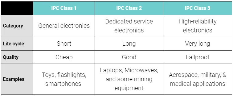
The standard organizes criteria into three product classes based on reliability needs, allowing flexibility for different project levels. Class 1 suits general consumer gadgets, Class 2 fits dedicated hobby or commercial uses, and Class 3 targets high-reliability applications. Hobbyists typically aim for Class 1 or 2 to balance quality and practicality. By referencing these classes, you align your work with industry-accepted norms right from your workbench.
Why IPC-A-610 Matters for Electronic Hobbyists
In the world of DIY electronics, a shaky solder joint or misaligned component can turn an exciting project into a frustrating debug session. IPC-A-610 provides a clear benchmark, explaining electronic assembly standards in a way that prevents common pitfalls and enhances reliability. For beginners, it demystifies what "good enough" looks like, reducing guesswork during inspections. Hobby projects often evolve into shared designs or small runs, where meeting these basics builds credibility and avoids failures in real-world use. Adopting IPC-A-610 principles early fosters better habits, like proper flux cleanup, that pay off in durable assemblies. Ultimately, it bridges the gap between casual tinkering and professional-grade results.
Consider how poor assembly leads to intermittent connections or overheating—issues that plague many first-time builds. This standard equips you to spot these proactively, saving time and components. Its visual nature makes it perfect for self-taught makers without formal training.
Understanding the Three Product Classes
IPC-A-610 divides assemblies into Class 1, Class 2, and Class 3, each with escalating criteria tailored to end-use demands. Class 1, for general electronics like toys or basic appliances, allows wider tolerances for solder appearance and placement, ideal for hobbyist prototypes where cost and speed matter most. Class 2 steps up for continued performance in consumer or industrial gadgets, demanding better wetting and fewer voids in joints. Class 3, reserved for mission-critical devices, enforces the tightest rules on dimensions, cleanliness, and damage to ensure long-term reliability.
Hobbyists benefit most from Class 1 and 2, as they match typical project scopes without overwhelming complexity. For instance, Class 1 permits minor solder ball offsets, while Class 2 requires precise alignment. Choosing the right class upfront guides your soldering technique and inspection focus. This classification system ensures your efforts scale with ambition, from simple LED blinkers to robust sensor arrays.
Key Inspection Criteria in IPC-A-610
Solder Joint Evaluation
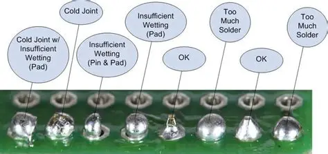
Solder joints form the backbone of any assembly, and IPC-A-610 details their ideal shape, coverage, and anomalies. Acceptable joints show smooth concave fillets with full wetting on leads and pads, free from cracks or excessive voids. Process indicators, like slight dewetting, signal potential process tweaks without rejection. Defects include bridging between pins or cold joints with rough surfaces that compromise conductivity. For through-hole parts, hole fill should reach certain levels per class, while surface-mount requires heel-toe fillet balance. Hobbyists can use a magnifying glass to check these, replicating pro inspections at home.
Component Mounting and Alignment
Proper component placement prevents stress on joints and ensures functionality. IPC-A-610 specifies tolerances for offset, tilt, and polarity, varying by class—Class 1 allows more leeway than Class 3. Misalignment can lead to open circuits or mechanical weakness, so centering parts over pads is key. For polarized capacitors or diodes, correct orientation avoids instant failures. Inspect by eye or with calipers for tombstoning in surface-mount, where one end lifts due to uneven heating. Consistent placement during soldering minimizes rework.
Cleanliness and Residue Control
Residues from flux or handling attract corrosion, undermining longevity. The standard requires boards free of visible flux, oils, or particles that could bridge contacts. Class 2 and above demand no white residue migration onto solder masks. Hobbyists often overlook this, but a quick isopropyl alcohol wipe followed by air dry meets basics. Ion contamination testing is advanced, but visual checks suffice for starters. Clean assemblies run cooler and more reliably.
Marking, Damage, and Conformal Coating
Legible markings on components and boards aid troubleshooting and traceability. IPC-A-610 flags smudged labels or scratches as issues if they obscure info. Mechanical damage like bent leads or cracked boards gets classified by severity. Conformal coatings, when applied, must cover evenly without bubbles or runs. For hobbyists adding protection, thin uniform layers prevent moisture ingress. These criteria round out a holistic inspection.
Best Practices for Applying IPC-A-610 in Your Workshop
Start by selecting your class based on project needs—Class 1 for quick prototypes, Class 2 for polished ones. Use quality solder and flux, maintaining steady iron temperatures around 350-400 degrees Celsius for lead-free. Practice on scrap boards to recognize fillets and wetting patterns. After assembly, perform a systematic visual pass: joints first, then placement, cleanliness, and damage. Document rejects with photos to track improvements. Pairing this with J-STD-001 process guidelines elevates results further.
Incorporate tools like a stereo microscope for fine work or UV light for residue detection. Preheat boards to avoid warpage, and reflow evenly for surface-mount. Test continuity post-inspection to validate visuals. These steps make IPC-A-610 actionable for hobbyists.
Troubleshooting Common Assembly Issues
Tombstoning plagues surface-mount newbies, often from rapid pad heating—slow your iron or use reflow ovens. Bridging happens with excess solder; wick away gently or mask pins. Non-wetting, where solder beads up, signals dirty pads—clean with alcohol and abrade lightly. Cold joints appear dull and grainy; reheat fully for shine. Excessive voids indicate trapped flux; adjust activation levels. By matching symptoms to IPC-A-610 criteria, you diagnose and fix efficiently.
Layered checks prevent cascading problems, like misalignment stressing joints.
Conclusion
Mastering IPC-A-610 basics transforms hobbyist assemblies from hit-or-miss to dependable. Its clear criteria for solder, placement, and cleanliness provide a roadmap for quality. Start with Class 1, progress as skills grow, and integrate inspections routinely. This what is IPC-A-610 foundation equips you for reliable projects and future scaling. Embrace these electronic assembly standards explained, and watch your builds thrive.
FAQs
Q1: What is IPC-A-610, and why should beginners care?
A1: IPC-A-610 is the leading standard for assessing electronic assembly acceptability, covering solder joints, components, and cleanliness in three classes. For beginners, it offers visual IPC-A-610 basics to self-inspect prototypes, catching defects early. This prevents failures in hobby projects like custom controllers. Applying it builds pro habits without complexity.
Q2: How do IPC-A-610 classes differ for hobbyists?
A2: Class 1 suits casual gadgets with lenient tolerances, while Class 2 demands better joint quality for reliable use. Hobbyists pick Class 1 for speed, upgrading to 2 for durability. Criteria tighten progressively on wetting and alignment. This IPC-A-610 introduction helps choose wisely.
Q3: What are the main IPC-A-610 criteria for solder joints?
A3: Key checks include fillet shape, wetting coverage, and void limits, classified as acceptable, indicator, or defect. Smooth, shiny joints without bridges pass Class 1 easily. Troubleshoot dullness as reheating cues. These electronic assembly standards explained guide visual reviews effectively.
Q4: Can hobbyists achieve IPC-A-610 compliance at home?
A4: Yes, with magnification, steady soldering, and cleanliness routines matching Class 1 or 2. Focus on J-STD-001 processes alongside for best results. Regular practice yields consistent assemblies. No fancy gear needed for basics.


