ALLPCB


Overview
Many implementations on the market use multi-touch gesture recognition. When multiple fingers touch the screen simultaneously, the system can recognize the movement direction of each finger and perform rotation, scaling, and translation operations, but it cannot determine the exact position of each finger. During two-point or multi-point touches, multiple peaks appear on the X and Y axes, making it impossible for the system to determine the precise touch locations. Points that are not actual touches are commonly called "ghost points".
Position-based Multi-touch vs. Gesture Recognition
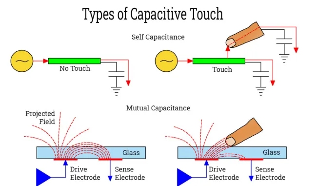
True multi-touch is position recognition that identifies the precise locations of touch points without ghost points. This technique is based on mutual-capacitance detection, determining touch locations from changes in coupling capacitance Cm at row-column intersections. When a finger touches, the mutual capacitance between rows and columns decreases, enabling detection of each touch point's position.
Implementing Two-point Touch on a Resistive Screen
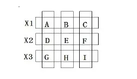
To implement two-point touch, each sensing unit must be independent and touch points must be confined within the same unit. Figure 1 shows a method for achieving multi-touch on a resistive touchscreen: apply voltage to the X1 electrode and read the X coordinates detected by touch units A, B, and C from the Y1, Y2, and Y3 electrodes; in subsequent cycles, read the coordinates for X2 and X3. After acquiring the X coordinates for all sensing units, apply voltage to the Y electrodes in turn to obtain the Y coordinates for each unit, thereby achieving two-point touch.
Contact Resistance and False Touches
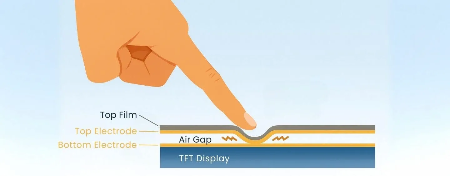
When the screen surface is touched, the upper ITO conductive layer deforms downward and contacts the lower ITO layer. There is a contact resistance between the two ITO layers at the contact point, and the resistance decreases as touch pressure increases. By measuring the corresponding resistance, touch position can be obtained. However, to correctly identify two-point touches, non-touch points must be eliminated first. Non-touch points are inadvertent contact points. These are random and not valid touches. For example, with very light pressure, the ITO layer may be near the conduction threshold; such contacts are non-touch points. These involuntary contacts are meaningless for detection and must be removed.
Given the randomness of non-touch points, a two-measurement method can eliminate them. If the first measurement yields a valid value but the second measurement exceeds the resistance range specified for the touchscreen and is very large, it is considered invalid and the point is treated as a non-contact point and discarded. Conversely, if the second measurement falls within the specified resistance range, it is regarded as a valid touch point.
Pressure, Contact Resistance, and Coordinate Accuracy
Different touch pressures produce different contact resistances in the ITO layer; that is, light and hard touches generate different resistances. A controller chip can measure contact resistance magnitude but cannot distinguish between a light and a hard touch. This only affects the accuracy of determining touch coordinates and therefore affects touchscreen reliability. Figure 2 shows a schematic of a light touch.
In current schemes, contact resistance and pressure are important factors affecting coordinate accuracy. If contact resistance is not greater than the sheet resistance, coordinate accuracy is not affected; if greater than the sheet resistance, jump points will occur. For example, a light touch at a point may cause incomplete circuit conduction, appearing as a large measured resistance compared with the actual value, causing its coordinate to jump backward. Conversely, a heavy touch shifts the coordinate forward. Thus light and heavy touches significantly affect the measured contact resistance; contact resistance is inversely proportional to pressure.
Technical manuals for some four-wire resistive touchscreens show they typically use a test condition of contact resistance less than 2 kΩ to specify minimum pressure. Under normal pressure, contact resistance is typically about 2 kΩ; with smaller pressure, contact resistance exceeds 2 kΩ. Therefore measured results dynamically vary with applied pressure; if the force at a point varies, the measured coordinate is uncertain, so the measurement method needs improvement.
Improving Measurement by Averaging
Decompose a full touch cycle as follows: (1) finger contacts the screen surface, (2) pressure increases gradually, (3) pressure is held, (4) finger is lifted, (5) pressure decreases gradually, (6) finger leaves the screen, completing the touch cycle. From this decomposition, finger pressure on the screen is not constant. By sampling the pressure and contact resistance at different stages and computing the average, the result will more closely reflect actual data; this is the main reason for averaging. Averaging can simulate the whole touch process and eliminate cases where pressure is unstable during initial, middle, or final contact.