ALLPCB


Utility companies focused on green power, efficiency, and adoption of smart grid technologies are upgrading conventional substations to digital substations.
Substation roles and traditional measurement
Substations interconnect different voltage levels and form a key link between transmission, distribution, and consumption. Primary devices located at the substation switchyard, such as power transformers, circuit breakers, and switches, protect and manage the power system. Auxiliary devices, including protection relays and terminal units, are typically installed away from the control-room panels in the switchyard to protect, control, and monitor the primary equipment.
Conventional instrument transformers such as potential transformers (PTs) and current transformers (CTs) measure the high voltage and currents flowing through primary equipment. Copper wiring connects the transformers' analog outputs to auxiliary devices, and the number of copper conductors increases with the application.
Figure 1 shows discrete CT and PT wiring used for protection, control, and monitoring. The large number of copper conductors increases installation and maintenance complexity and raises the potential for costly failures. In addition, multiple transformers mean that digital representations of primary currents and voltages differ between devices, which limits system performance and reliability.
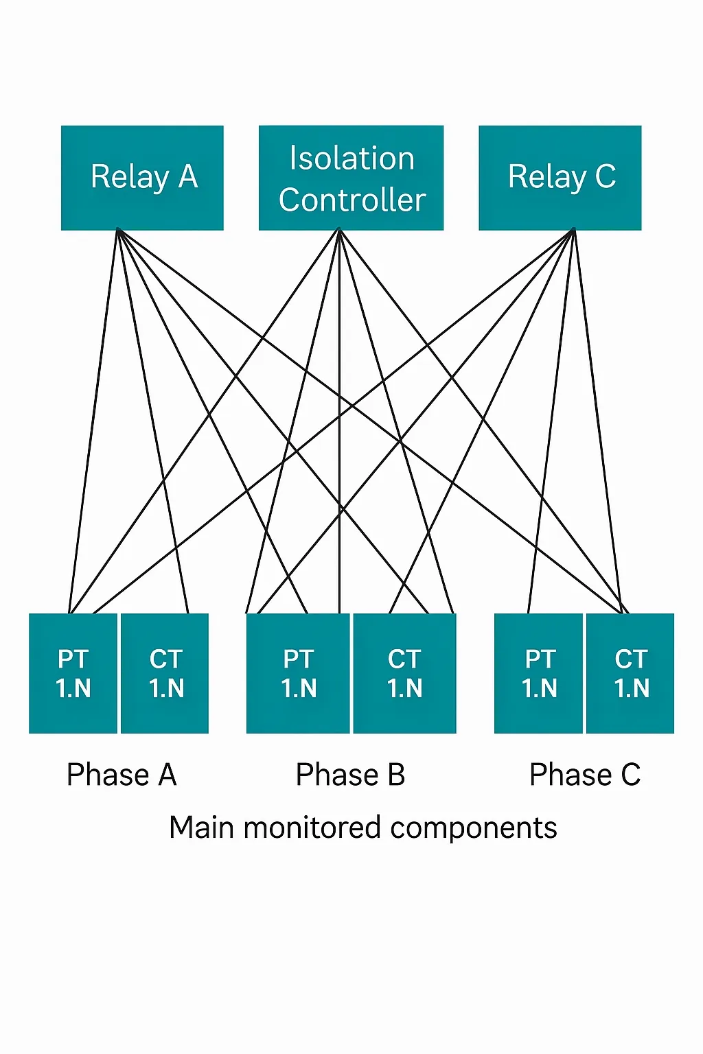
Figure 1: CT and PT wiring in a conventional substation using copper conductors.
Digital substations
A digital substation is part of a hierarchical system that includes all protection, control, measurement, condition monitoring, recording, and supervisory systems related to primary processes.
Digital substations use optical fiber cables to replace hundreds or thousands of meters of copper cabling between the switchyard and intelligent electronic devices (IEDs). By digitizing process-related data using conventional or nonconventional instrument transformers (NCITs) and merging units, and transmitting over fiber, digital substations reduce copper usage, resulting in simpler, more compact, and more efficient installations.
Digital substation architecture
Per the International Electrotechnical Commission (IEC) 61850 standard, the digital substation architecture comprises three levels: the process level, the bay level, and the station level.
Each level performs specific functions and the applications work together to deliver digital substation capabilities.
The process level includes power transformers, instrument transformers, and switching devices. It is the interface between primary devices and auxiliary (protection and control) devices. In traditional substations this interface uses hard-wired copper cables; currents and voltages are delivered at standardized auxiliary signal levels to protection and control panels, while control cables send and receive status information. In digital substations, all data—analog and binary—is digitized near the signal source and sent over fiber using IEC 61850-9-2 to IEDs.
The bay level includes auxiliary devices or IEDs such as bay controllers, protection relays, fault recorders, and meters. Because data acquisition happens at the process level, IEDs no longer require analog inputs. Merging inputs can also reduce or eliminate the need for binary inputs, enabling more compact devices that typically occupy half the space of conventional equipment. IEDs execute protection and control algorithms and logic, make trip/no-trip decisions, and provide IEC 61850-based communication for lower (process) and upper (station) levels over Ethernet. Redundant communication networks are a typical requirement to ensure high availability and reliability. The IEC 62439 standards—High-availability Seamless Redundancy (HSR) and Parallel Redundancy Protocol (PRP)—facilitate IED interoperability and integration of devices from multiple vendors into the substation network.
The station level includes the substation computer, Ethernet switches, and gateways. In addition to the traditional supervisory control and data acquisition (SCADA) bus, the station bus provides expanded communication functionality by allowing multiple clients to exchange data, supporting peer-to-peer device communication, and linking gateways for inter-substation and wide-area communication. Station-level devices can include the substation human-machine interface (HMI), engineering workstations for IED access, local aggregation and archiving of power-system data, SCADA gateways, proxy servers for remote HMIs, and controllers.
Measuring electrical parameters with merging units
Merging units convert instrument transformer outputs into standardized Ethernet-based data outputs and implement IEC 61850.
In a digital substation, rather than routing sensor outputs to bay-level protection and control devices, merging units are placed near the sensors connected to primary equipment at the process level.
Merging units convert analog signals (voltage, current) into sampled values based on IEC 61850-9-2 for protection, metering, and control, and communicate digitally with IEDs in the substation, as shown in Figure 2. Key functions include analog-to-digital conversion, resampling, synchronization to a global time reference, formatting samples into IEC 61850-9-2 messages, and communicating with IEDs via a fiber Ethernet interface.
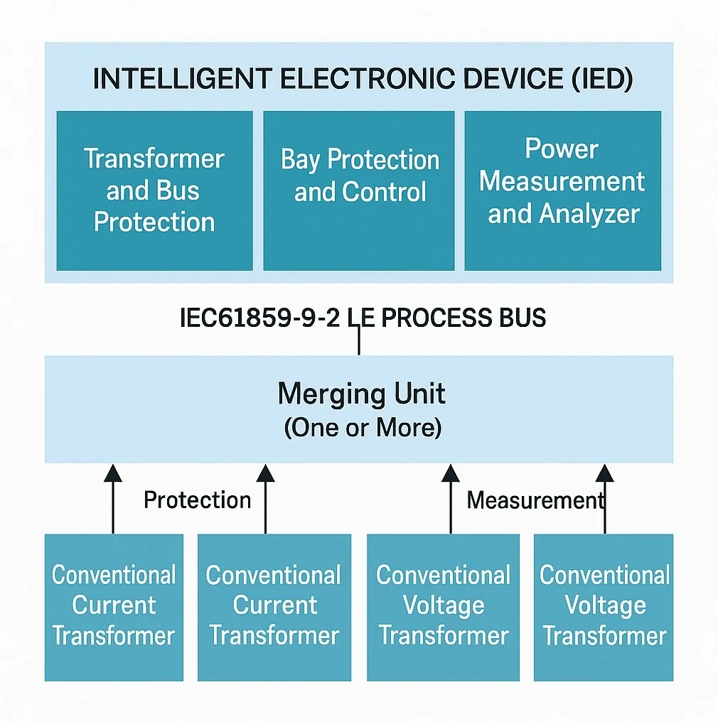
Figure 2: Merging unit with conventional transformers.
Merging units perform the necessary processing to generate accurate, time-aligned sampled-value output streams according to IEC 61850-9-2. This processing includes sampling analog values, maintaining an accurate real-time reference, formatting messages as sampled values, and publishing a single data source to protection, metering, and control devices.
Key technical drivers for merging units
- High-performance precision ADCs with excellent AC specifications, high input impedance, low measurement drift, and low power consumption.
- A signal processor capable of real-time sampled-value processing and implementing substation communication protocols.
- High-speed Ethernet physical layer with fiber interfaces (typically 100 Mbps, moving toward 1 Gbps).
- Precise time synchronization (microsecond), including GPS-based 1 pps input and IEEE 1588 Precision Time Protocol.
- Use of safer and more accurate NCITs.
- Support for IEC 61850 standards, including IEC 61850-8-1, generic object-oriented substation event (GOOSE) messaging, and IEC 61850-9-2 sampled values.
- IEC 62439-3 redundancy, including HSR for ring topologies and PRP for star topologies.
- Network security to ensure secure and authenticated communications.
Main design challenges for merging units
Designing a merging unit involves several challenges that affect architecture and performance, including:
- Selecting scalable ADCs that synchronize sampling to an accurate global time reference.
- Connecting multiple ADCs to a host processor and capturing data in real time to increase the number of analog input channels.
- Real-time capture of samples to meet protection and metering sampling requirements.
- Using Ethernet communication with fiber interfaces.
- Implementing the IEC 61850-9-2 communication protocol so sampled data can be shared with multiple users without packet loss.
- Making the protocol stack compatible with redundancy protocols and time synchronization methods such as IEEE 1588 PTP, HSR, and PRP.
- Implementing multiple I/O, including 16 or more binary inputs, wide AC and DC inputs, DC sensor I/O, and expansion options.
- Ensuring reliable operation in harsh switchyard environments with high transients, elevated ambient temperatures, and magnetic fields.
Addressing merging unit design challenges
Texas Instruments supplies integrated circuits and reference designs that address many of these challenges.
Merging units comprise multiple interconnected subsystems that perform signal scaling/capture, processing, and communication functions. Components and their roles include:
- Processor module (for example AM3359, AM4372, AM5706, or AM6548) with a programmable real-time unit industrial communication subsystem (PRU-ICSS) connected to ADCs, a digital signal processor (DSP) core for electrical parameter processing and algorithms, and an Arm Cortex-A15 microprocessor subsystem for external communication, user interface, and execution of substation communication protocols.
- Ethernet interface with fiber or copper options (for example DP83822, DP83840) connected via MII or RMII and using hardware-assisted IEEE 1588 PTP time-stamping to synchronize communication at 100 Mbps.
- AC/DC supplies with wide input, high efficiency, synchronous-rectified power supplies (for example UCC28600, UCC28740, UCC24630).
- DC/DC power rails (for example LMZM33604, TPS82085) featuring compact, efficient power modules with integrated inductors and >2 A load current capability, fast transient response, and reduced EMI from integration of controller, FETs, and inductor in one package.
- Memory termination (for example TPS51200, TPS51116) using JEDEC-compliant source or sink DDR termination or integrated DDR power management devices with synchronous buck controller, LDO, and buffered reference.
- AC analog input module (for example OPA4188, THS4541, ADS8588S, ADS8688, AMC1306x) supporting AC voltage and current inputs for protection, monitoring, and metering. Gain amplifiers scale sensor outputs to the ADC input range. 16-bit, 18-bit, or 24-bit successive-approximation-register or delta-sigma ADCs capture samples at 80 or 256 samples per cycle (or higher), synchronized to a global time reference using 1 pps or instrument-bay group synchronization.
- DC analog input or RTD module (for example ADS1248, ADS124S08) for bidirectional or unidirectional DC voltage or current control functions and remote device communication. 24-bit delta-sigma ADCs improve measurement range and resolution.
- Binary input module for battery monitoring (for example ADS7957, ISO7741, ISOW7841) providing interlocks and indicating configuration changes and status. Compared with designs based on optocouplers and Zener diodes, ADC- and digital-isolator-based architectures improve measurement accuracy and reduce circuit complexity by using fewer components.
- Relay or high-speed digital output modules (for example TPS7407, DRV8803) for alarms and external breaker operations.
- Onboard transient protection for analog inputs (for example TVS3300 or TVS3301) and board-level diagnostics (for example HDC2010, TMP423, TMP235) to monitor environment for compensation of measurement drift.
Connecting merging units to instrument transformers
Merging units connect to various instrument transformers for measurement, including conventional instrument transformers, NCITs (such as optical CTs), Rogowski current sensors, and resistor-capacitor voltage dividers (RCVTs). NCITs connected to a merging unit provide options for metering, protection, and control precision from a single device. NCIT technologies reduce transformer size and weight, saving space and cost.
NCIT advantages include a wide dynamic range with improved measurement accuracy due to reduced sensor saturation effects, higher accuracy when measuring transients and harmonics, and improved safety from reduced internal arcing and secondary open-circuit faults.
Conclusion
Merging units are a key enabler for utilities migrating from conventional to digital substations. By reducing the number of copper conductors and digitizing data near primary equipment, merging units simplify installation complexity and improve measurement accuracy. Merging units can connect to NCITs, which are smaller, safer, and more accurate while offering a wider measurement range and lower cost. Fiber communication interfaces improve immunity to switchyard interference and minimize communication failures.
Other benefits of merging units include extended life, improved reliability, and increased availability of primary equipment. Integrated solutions across analog, power, interface, timing, and embedded processing help merging unit designers reduce design effort and optimize cost.