ALLPCB


RF refers to the electromagnetic frequency range that can radiate into space, from 300 kHz to 300 GHz. RF technology is now used across communications, test and measurement instruments, industry, and aerospace.
The rollout of 5G has increased public familiarity with these concepts. The following uses simple analogies to explain key RF and microwave phenomena.
1. Electromagnetic waves
Electromagnetic waves are a form of energy. Any object above absolute zero emits electromagnetic waves. Electric current produces a magnetic field, and a changing magnetic field induces current. A changing electric field and a changing magnetic field form a single inseparable field.
At low-frequency oscillations, the interchange between electric and magnetic energy is slow and most energy returns to the original circuit, so there is little radiation. At high-frequency oscillations, the interchange is rapid and energy cannot all return to the source. Electric and magnetic energy propagate through space as electromagnetic waves, carrying energy without requiring a medium. This is radiation.
2. Direct wave
Analogy: In billiards, if a ball is struck through its center with no obstacles, it moves in a straight line, like a direct wave.
A radio wave that travels in a straight line from a transmitting antenna to a receiving point is called a direct wave. Free-space propagation is the ideal case where the wave travels in vacuum without absorption, reflection, or scattering, equivalent to direct-wave propagation.
3. Reflected wave
Analogy: In billiards, when a ball hits the table rail, it follows reflection rules where the angle of incidence equals the angle of reflection, similar to reflected waves.
In wireless coverage planning, incident angle matters. For example, base station candidates should not be too far from railway lines; large incident angles reduce the signal entering train cars. Radio waves that reach the receiver after reflecting off the ground or other obstacles are reflected waves.
Reflection occurs at interfaces between media with different densities. The greater the difference in medium density at the interface, the more reflection and the less refraction. Smaller incident angles produce less reflection and more refraction.
4. Diffracted wave
Analogy: In billiards, if the cue ball grazes another ball and changes direction to pass around an obstacle, that resembles diffraction.
When the line of sight between transmitter and receiver is blocked by a sharp edge, radio waves can bend around the obstacle and propagate to the receiver; this is diffraction. The wave path changes or bends, and secondary waves from the obstructing surface spread into space, even behind the obstacle. Diffraction loss is the attenuation caused by obstacles to radio-wave transmission.
5. Scattered wave
Analogy: In billiards, if many balls are clustered closely and the cue ball hits them, many balls scatter in different directions, like scattering.
Scattering occurs when the propagation medium contains objects smaller than the wavelength and the number of scatterers per unit volume is large. Scattered waves originate from rough surfaces, small objects, or irregular shapes. In practical systems, leaves, street signs, and lamp posts cause scattering.
6. Skin effect
Analogy: After heavy rain, a muddy road may have a central water-filled trench, forcing people to walk along the drier edges and reducing usable width.
Because the reactance inside a conductor opposes AC more than the surface, AC current density in a conductor is uneven: surface current density is higher, reducing effective cross-sectional area and increasing loss. This is the skin effect. The higher the AC frequency, the more pronounced the skin effect; at high enough frequencies, current effectively flows only on the conductor surface.
Applications: hollow conductors can replace solid conductors to save material; in high-frequency circuits, bundles of insulated fine wires can reduce the skin effect.
7. Multipath effect
Analogy: Pouring water at the top of a small mound causes water to flow in many directions, seep into the soil, or converge at a low point by different paths.
Multipath refers to the situation where signals travel from transmitter to receiver via multiple paths with different delays and attenuations. Paths can be direct, reflected, or diffracted. At the receiver, identical signals arriving by different paths can add constructively or destructively, increasing or decreasing the received signal energy.
8. Shadowing
Analogy: When sunlight falls on the ground, trees and buildings cast shadows that are not completely dark but have much weaker light intensity.
9. Fresnel zone
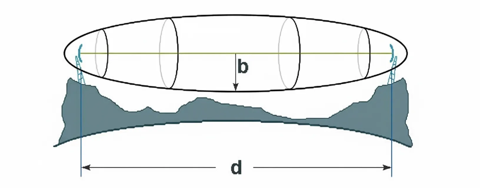
Analogy: A person's most effective field of view is roughly an ellipsoid; objects outside that ellipsoid are visible but less clear. An experienced shooter focuses within a small ellipsoid between shooter and target.
The Fresnel zone is an ellipsoid with the transmit and receive antennas at its two foci. The radius of that ellipsoid defines the first Fresnel radius. In free space, most electromagnetic energy from transmitter to receiver travels through the first Fresnel zone; if the first Fresnel zone is not obstructed, propagation approximates free-space conditions.
To ensure communication, antenna heights should be set so obstacles intrude no more than about 20% into the Fresnel zone; otherwise multipath effects can degrade or interrupt communication.
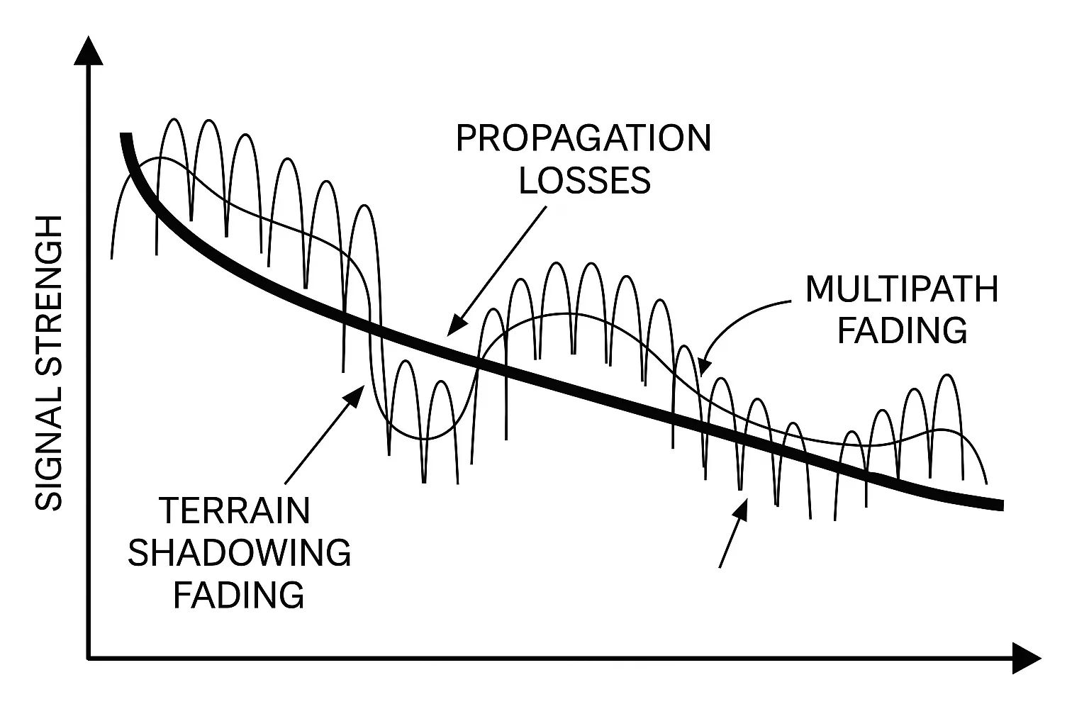
10. Slow fading and fast fading
Analogy: During a stock market decline, intraday fluctuations may be intense while a 5-week moving average changes slowly; instantaneous, rapid price swings resemble fast fading.
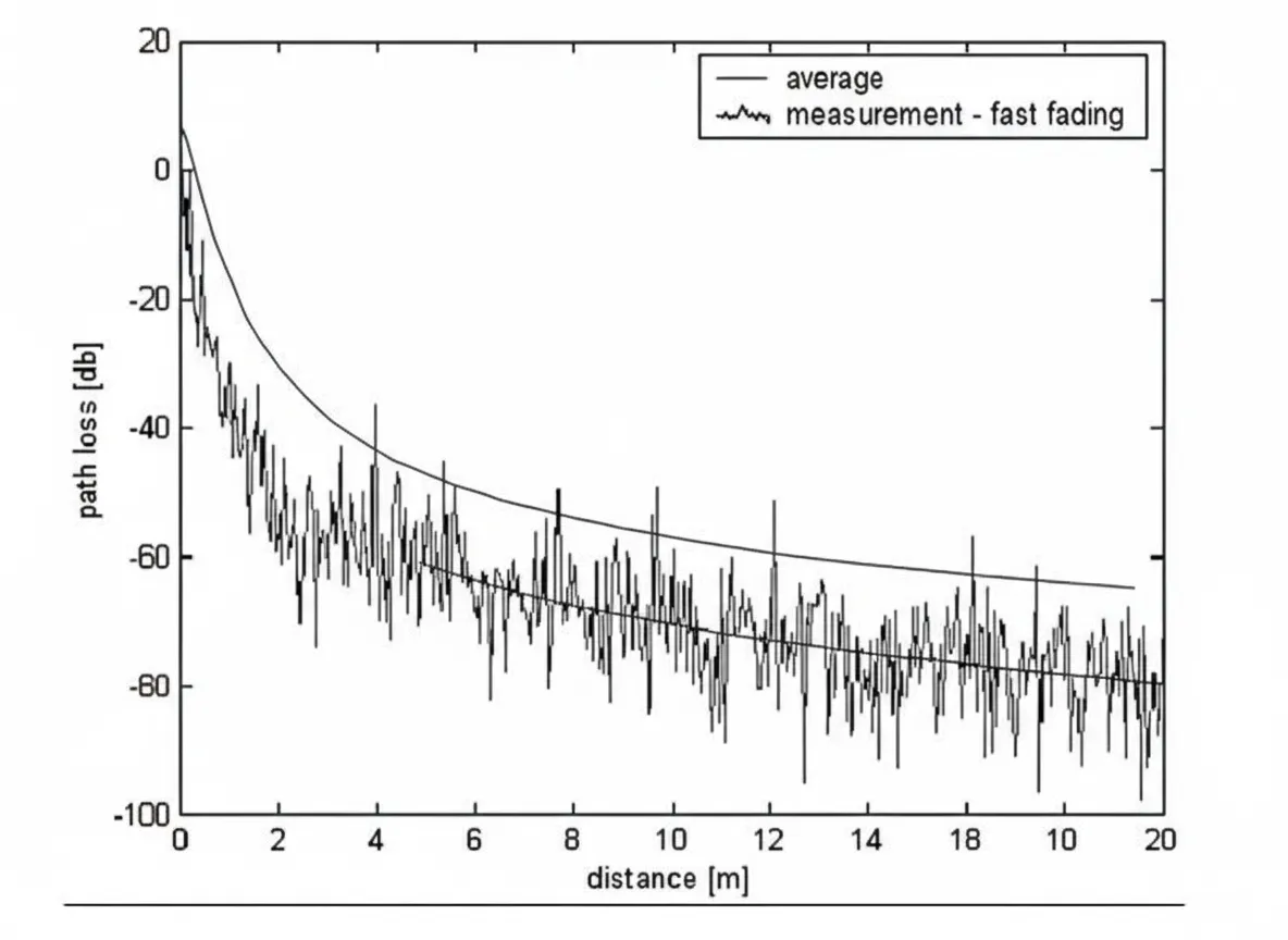
Slow fading refers to the slow variation of the median signal strength. It represents the median after weighting and averaging instantaneous values and reflects average received power over ranges on the order of hundreds of wavelengths; slow fading typically follows a log-normal distribution.
Causes of slow fading include path loss and shadowing by obstacles.
Fast fading is the rapid fluctuation of instantaneous received signal strength. It is caused by multipath signals from terrain, objects, and moving bodies adding at the receiver with differing phase, frequency, and amplitude, producing rapid amplitude variations. High-speed motion of a mobile receiver causes Doppler shifts that also produce rapid amplitude changes.
Fast fading can be categorized as:
- Space-selective fading due to multipath causing location-dependent fading characteristics.
- Frequency-selective fading when carrier bandwidth exceeds the channel's coherence bandwidth, causing distortion.
- Time-selective fading when multipath or Doppler spreads arrival times beyond the coherence time, causing time-domain distortion.