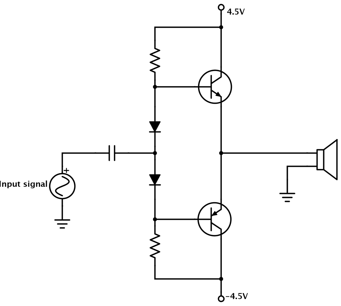
In practical circuit design, three main types of grounds are commonly used.
- Signal Ground: This can be further divided into digital and analog grounds. Power ground is often considered a type of analog ground. These grounds are fundamental to the circuit board's functionality.
- Protective Ground (Earth): Typically found in AC-powered and high-voltage products, protective ground is a safety feature that connects to the earth ground to prevent electric shock.
- Chassis Ground: This refers to the connection point on a product's metal enclosure or other metallic structural components.
Common Grounding Problems
1. High Ground Resistance
Excessive ground resistance can render a grounding system ineffective or unstable, failing to properly dissipate electrical charge or fault currents. This can lead to equipment malfunctions, signal interference, or electric shock hazards. Hardware engineers must ensure ground resistance meets design specifications through proper layout and maintenance.
2. Ground Return Path Issues
In complex circuits, improper ground return paths or excessive return currents can cause ground loops. This often results in signal interference, increased noise, and degraded device performance. A careful analysis of the circuit layout is required to mitigate these issues.
3. Shared Ground Issues
When multiple devices share a common ground, inconsistencies in their grounding methods or significant differences in ground potential can create interference and unintended current loops. Engineers must ensure grounding consistency between interconnected devices to avoid these problems.
4. Electrostatic Discharge (ESD) Issues
ESD is a common problem with poor or non-existent grounding. An ESD event can damage or destroy sensitive electronic components. Implementing proper anti-static measures, such as ESD protection devices and a well-designed grounding system, is crucial to prevent ESD-related failures.
Grounding Connection Strategies
Connecting Digital and Analog Grounds
There are several schools of thought on how to handle digital and analog grounds:
One common approach is to completely separate the digital and analog ground planes to minimize interference between digital and analog circuits.
Another method is to connect the separate digital and analog ground planes at a single point on the board, often called a "star" ground point.
A third strategy is to use a single, unified ground plane for the entire board. In this layout, digital and analog components are physically partitioned into separate areas to keep their return currents from interfering with each other.
Chassis Ground Connections
The chassis ground can be connected in several ways depending on its intended function:
- Safety Protection: Connected to earth ground to protect users from electric shock.
- EMI Shielding: Connected to the metal shells of connectors to provide a continuous shield.
- ESD Path: Used as the primary path to safely discharge electrostatic buildup.
- Signal Ground Reference: Tied to the circuit board's signal ground. This can be implemented using single-point or multi-point grounding topologies depending on the application's frequency and EMI requirements.
 ALLPCB


