ALLPCB


Struggling with SMT assembly issues like poor solder joints or reflow soldering defects? Continuity testing is a critical step in troubleshooting surface mount technology (SMT) assemblies to ensure reliable performance. In this comprehensive guide, we’ll explore effective continuity testing techniques for SMT assembly testing, focusing on surface mount continuity, solder joint continuity, and how tools like automated optical inspection (AOI) can help identify and resolve common problems. Whether you're dealing with reflow soldering defects or verifying electrical connections, this blog will equip you with practical solutions to enhance your PCB quality.
What is SMT Assembly Testing and Why Does Continuity Matter?
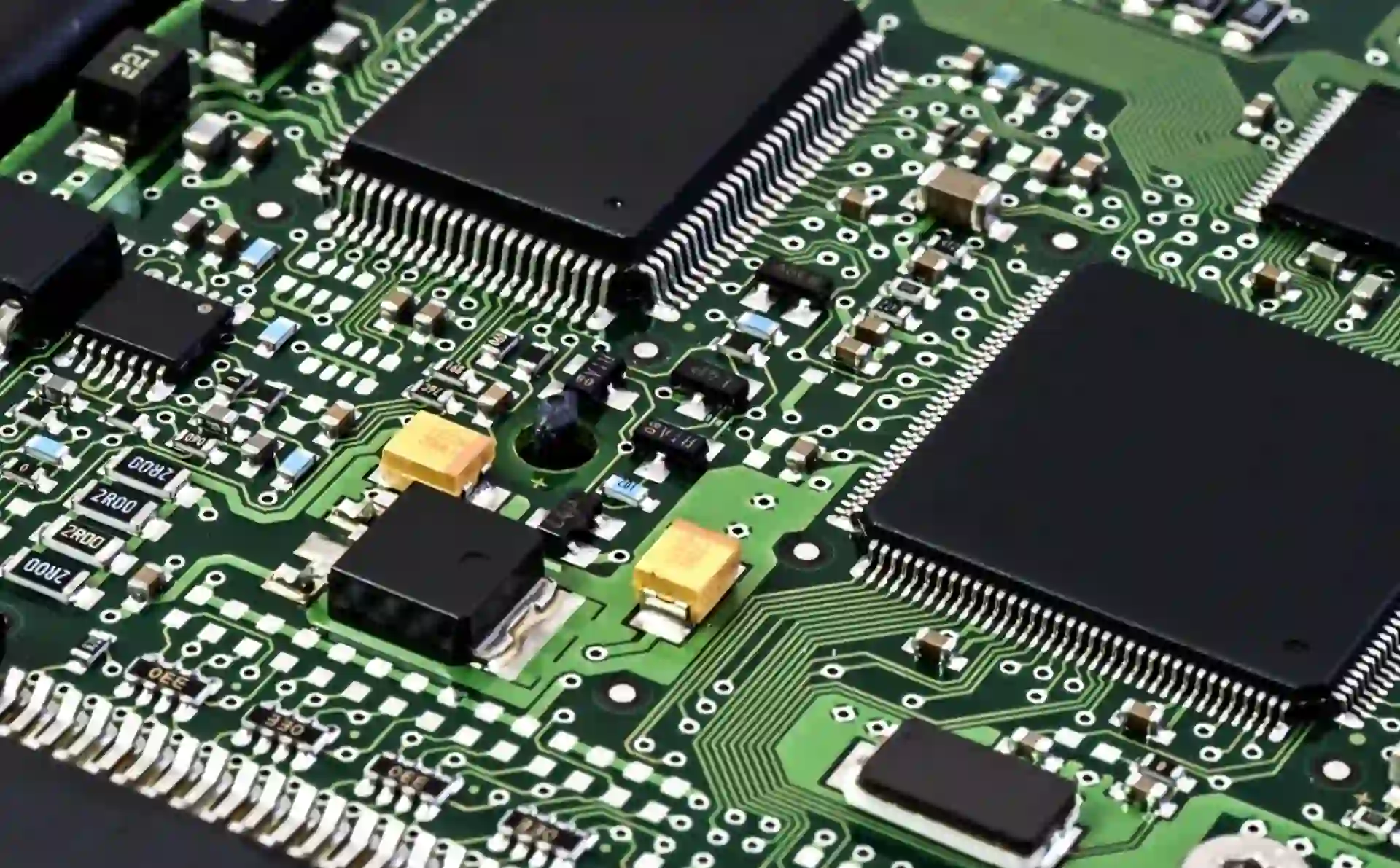
SMT assembly testing is the process of evaluating surface mount components and their connections on a printed circuit board (PCB) to ensure functionality and reliability. Continuity testing, a key part of this process, checks whether electrical paths between components are intact, confirming that current can flow without interruption. Poor continuity often points to issues like broken traces, defective solder joints, or misplaced components, which can lead to circuit failure.
Continuity is especially critical in SMT assemblies due to the small size of components and the precision required in soldering. A single faulty connection can compromise an entire device, making thorough testing essential for quality control in electronics manufacturing.
Understanding Common Issues in SMT Assemblies
Before diving into testing techniques, it’s important to recognize the common problems that affect SMT assemblies. These issues often manifest as continuity failures and can stem from various stages of the manufacturing process.
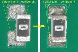
- Reflow Soldering Defects: During reflow soldering, components are bonded to the PCB using a heat profile. Defects like insufficient solder, cold joints, or tombstoning (where components lift on one side) can occur if the temperature profile is incorrect or if there’s uneven heat distribution. These defects often result in poor electrical connections.
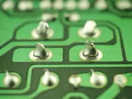
- Solder Joint Continuity Issues: Solder joints are the backbone of SMT assemblies. Cracks, voids, or insufficient solder can disrupt continuity, leading to intermittent or complete circuit failure.
- Component Misalignment: Tiny surface mount components can shift during placement or reflow, causing open circuits or shorts that affect continuity.
- PCB Warpage: Excessive heat or mechanical stress can warp the PCB, leading to strained solder joints and potential continuity breaks.
Identifying these issues early through effective testing techniques saves time, reduces costs, and ensures high-quality output in electronics production.
Continuity Testing Techniques for SMT Assemblies
Continuity testing is a fundamental method for troubleshooting SMT assemblies. Below, we explore several techniques tailored to surface mount continuity and solder joint integrity, providing actionable steps for engineers and technicians.
1. Manual Continuity Testing with a Multimeter
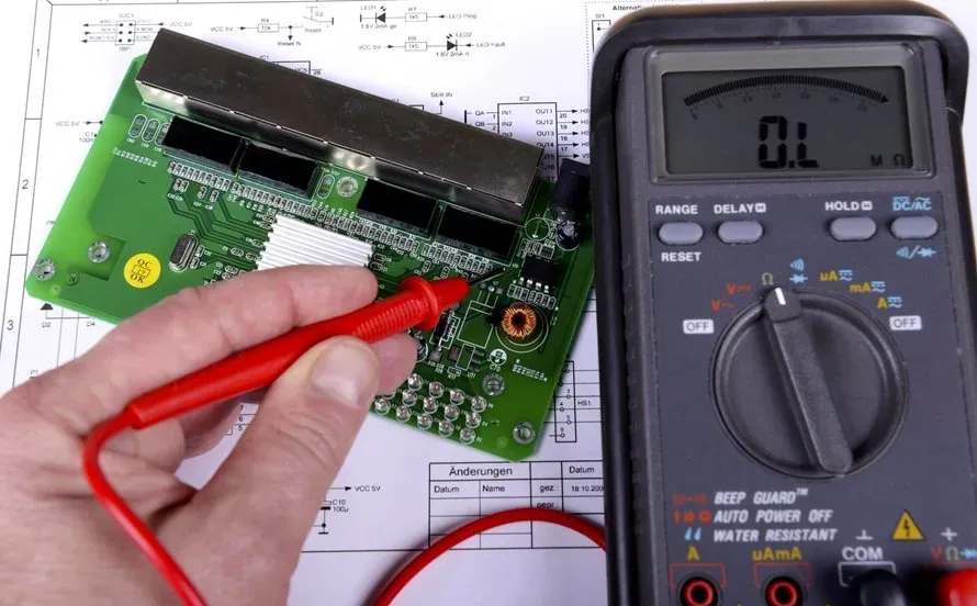
The simplest and most accessible method for checking surface mount continuity is using a digital multimeter set to continuity mode. This tool emits a beep when a complete electrical path is detected between two points.
Steps for Manual Testing:
- Power off the PCB and ensure it’s safe to test.
- Set the multimeter to continuity mode (often indicated by a diode symbol or sound wave icon).
- Place the probes on the two points of the circuit you’re testing, such as across a solder joint or between a component lead and a trace.
- Listen for a beep or check the display for a reading close to 0 ohms, indicating continuity. A reading of infinite resistance or no beep suggests an open circuit.
Key Tip: For SMT components, use fine-tip probes or needle probes to access tiny solder joints without damaging the board. Typical resistance for a good solder joint should be below 1 ohm, while anything higher may indicate a poor connection.
Limitations: Manual testing is time-consuming for complex boards with hundreds of connections and may miss intermittent issues. It’s best suited for small-scale troubleshooting or spot-checking.
2. In-Circuit Testing (ICT) for Comprehensive Analysis
In-circuit testing (ICT) is a more advanced method for SMT assembly testing, often used in high-volume production. ICT uses a bed-of-nails fixture or flying probe tester to check multiple points on the PCB simultaneously, verifying continuity, resistance, and component functionality.
How ICT Works:
- A custom fixture with probes contacts specific test points on the PCB.
- The system measures electrical parameters, including continuity between points, to detect open circuits or shorts.
- Results are compared against a known good board or design specifications to identify defects.
Advantages: ICT can test hundreds of connections in seconds, making it ideal for detecting solder joint continuity issues across an entire assembly. It’s highly accurate, with modern systems achieving fault detection rates above 90%.
Limitations: ICT requires custom fixtures, which can be costly and time-consuming to design for each PCB layout. It also struggles with components like ball grid arrays (BGAs) where solder joints are hidden beneath the package.
3. Automated Optical Inspection (AOI) for Visual Defect Detection
Automated Optical Inspection (AOI) is a non-contact testing method widely used in SMT assembly testing to identify visual defects that impact continuity. AOI systems use high-resolution cameras and image processing software to scan the PCB surface after reflow soldering.
What AOI Detects:
- Misaligned or missing components that could cause open circuits.
- Visible reflow soldering defects like insufficient solder or bridging between pads.
- Tombstoning or lifted components that disrupt solder joint continuity.
Benefits of AOI: AOI machines can inspect thousands of components per minute, achieving defect detection rates of over 95% for visible issues. They’re programmable to match specific design parameters, ensuring consistent results.
Limitations: AOI cannot inspect hidden solder joints, such as those under BGAs, and may miss subtle defects like micro-cracks in solder joints. It’s often used alongside other methods like X-ray inspection for comprehensive testing.

4. X-Ray Inspection for Hidden Solder Joints
For components with hidden solder joints, such as BGAs or chip-scale packages, X-ray inspection is a powerful tool to assess solder joint continuity. This method uses X-rays to penetrate the PCB and create detailed images of internal structures.
How X-Ray Inspection Helps:
- Detects voids or cracks in solder balls under BGAs that could interrupt continuity.
- Identifies insufficient solder or misalignment not visible to the naked eye or AOI.
- Provides a non-destructive way to inspect complex assemblies.
Key Data: Studies show that up to 30% of BGA failures are due to voids or poor solder joint integrity, which X-ray systems can detect with accuracy rates exceeding 90%.
Limitations: X-ray equipment is expensive and requires trained operators. It’s typically used for high-value or critical applications rather than routine testing.
Troubleshooting Reflow Soldering Defects Impacting Continuity
Reflow soldering defects are a leading cause of continuity issues in SMT assemblies. Understanding how to troubleshoot these defects can significantly improve assembly quality.
Common Reflow Soldering Defects and Fixes
- Cold Solder Joints: These occur when solder doesn’t fully melt, resulting in weak, unreliable connections. Test with a multimeter for high resistance (above 1 ohm). Fix by adjusting the reflow profile to ensure peak temperatures reach 235-250°C for lead-free solder.
- Solder Bridging: Excess solder can create unintended connections between pads, causing shorts. Use AOI to detect bridges and rework with a soldering iron or desoldering braid.
- Tombstoning: Components lift on one side due to uneven heating or pad design. Check with AOI and correct by balancing thermal profiles or redesigning pads for equal solder volume.
- Voids in Solder Joints: Air pockets in solder reduce conductivity and strength. Use X-ray inspection to identify voids and optimize solder paste application or reflow conditions to minimize them.
Pro Tip: Regularly calibrate reflow ovens to maintain consistent temperature profiles. A variance of just 5°C can lead to defects like cold joints or overheating, impacting solder joint continuity.
Best Practices for Ensuring Continuity in SMT Assemblies
Beyond testing, adopting best practices during design and assembly can prevent continuity issues from arising. Here are actionable tips for engineers:
- Design for Testability: Include accessible test points on the PCB layout for manual or ICT testing. Ensure pads and traces are sized appropriately for reliable soldering.
- Optimize Solder Paste Application: Use precise stencil designs to apply consistent solder paste volumes, reducing the risk of insufficient solder or voids.
- Control Reflow Profiles: Tailor the reflow oven temperature profile to the specific components and solder type. For lead-free solder, aim for a peak temperature of 240-260°C with a time above liquidus of 60-90 seconds.
- Combine Testing Methods: Use a mix of manual testing, ICT, AOI, and X-ray inspection to cover all aspects of continuity, from visible defects to hidden issues.
- Regular Maintenance: Keep assembly and testing equipment in top condition to avoid errors caused by faulty tools or machines.
Conclusion: Mastering Continuity Testing for Reliable SMT Assemblies
Troubleshooting SMT assemblies requires a deep understanding of continuity testing techniques to ensure reliable electrical connections and high-quality PCBs. From manual multimeter checks to advanced methods like ICT, AOI, and X-ray inspection, each approach offers unique benefits for detecting issues like reflow soldering defects and solder joint continuity failures. By combining these techniques with best practices in design and assembly, engineers can minimize defects and enhance the performance of surface mount assemblies.
At ALLPCB, we’re committed to supporting your SMT assembly testing needs with cutting-edge solutions and expertise. Whether you’re tackling surface mount continuity challenges or optimizing your production process, the right testing strategy is key to success in electronics manufacturing.