 ALLPCB


Selecting the right PCB connector for your project is crucial for ensuring reliable performance, efficient power delivery, and long-term durability. Whether you're designing a compact consumer device or a complex industrial system, understanding the types of PCB connectors, connector current rating, connector voltage rating, connector mounting options, and connector reliability considerations can make or break your design. In this comprehensive guide, we'll walk you through everything you need to know to make an informed decision, from the basics to advanced tips for optimizing your PCB layout.
Why Choosing the Right PCB Connector Matters
PCB connectors act as the critical link between components, boards, and external systems in electronic devices. A poorly chosen connector can lead to signal loss, power inefficiency, or even complete system failure. By focusing on key factors like current and voltage ratings, mounting styles, and reliability, you can avoid costly redesigns and ensure your project meets performance expectations. Let’s dive into the details to help you navigate this essential aspect of PCB design.
What Are PCB Connectors?
PCB connectors are electromechanical components that facilitate electrical connections between a printed circuit board (PCB) and other boards, wires, or devices. They come in various shapes, sizes, and configurations, each suited for specific applications. From transmitting power to handling high-speed data signals, connectors play a vital role in the functionality of electronic systems. Understanding the different types of PCB connectors is the first step in choosing the right one for your project.
Common Types of PCB Connectors
Let’s explore the most widely used types of PCB connectors and their typical applications:
- Board-to-Board Connectors: These connectors link two PCBs together, often used in compact devices where space is limited. They are ideal for applications requiring high-density connections, such as smartphones or modular systems. Common configurations include mezzanine connectors with stack heights ranging from 5mm to 30mm.
- Wire-to-Board Connectors: Used to connect wires to a PCB, these are essential for power delivery or sensor integration. They often support a wide range of wire gauges, typically from 18 AWG to 30 AWG, depending on the current requirements.
- Wire-to-Wire Connectors: Though not directly mounted on a PCB, these connectors are often used in conjunction with PCB systems to join wires outside the board. They’re common in automotive and industrial applications.
- RF Connectors: Designed for high-frequency signals, RF connectors are critical in communication devices. They maintain signal integrity at frequencies up to 6 GHz or higher, making them suitable for wireless systems.
- Power Connectors: These handle high current and voltage, often used in power supply units. They can support currents from 10A to 50A or more, depending on the design.
- USB Connectors: Widely used for data transfer and power delivery, USB connectors (like Type-A, Type-C, or Micro-USB) are found in consumer electronics. They typically support voltages of 5V and currents up to 3A for charging.
Key Electrical Specifications: Connector Current Rating and Voltage Rating
When selecting a connector, two of the most critical specifications to consider are the connector current rating and connector voltage rating. These parameters determine whether the connector can safely handle the electrical demands of your project.
Connector Current Rating
The connector current rating indicates the maximum amount of current (in amperes, A) that a connector can carry without overheating or degrading. Choosing a connector with an insufficient current rating can lead to thermal damage, increased resistance, or even fire hazards. For example:
- A small signal connector might be rated for 1A to 2A, suitable for low-power data lines.
- A power connector for industrial equipment might handle 20A to 50A, designed for high-power applications.
Always select a connector with a current rating at least 25% higher than your project’s maximum expected current to account for surges and ensure safety. For instance, if your circuit draws 8A, opt for a connector rated for at least 10A.
Connector Voltage Rating
The connector voltage rating specifies the maximum voltage (in volts, V) the connector can withstand without risking dielectric breakdown or arcing. This is especially important in high-voltage applications where insulation failure could cause catastrophic damage. Examples include:
- Low-voltage connectors rated for 5V to 12V, common in consumer electronics.
- High-voltage connectors rated for 600V or more, used in industrial power systems.
Similar to current ratings, it’s wise to choose a connector with a voltage rating higher than your system’s operating voltage. If your design operates at 48V, look for a connector rated for at least 60V to provide a safety margin.
Exploring Connector Mounting Options
The way a connector is physically attached to a PCB—known as its mounting style—impacts both the design process and the final product’s durability. Understanding connector mounting options helps you choose a style that fits your manufacturing process and application needs.
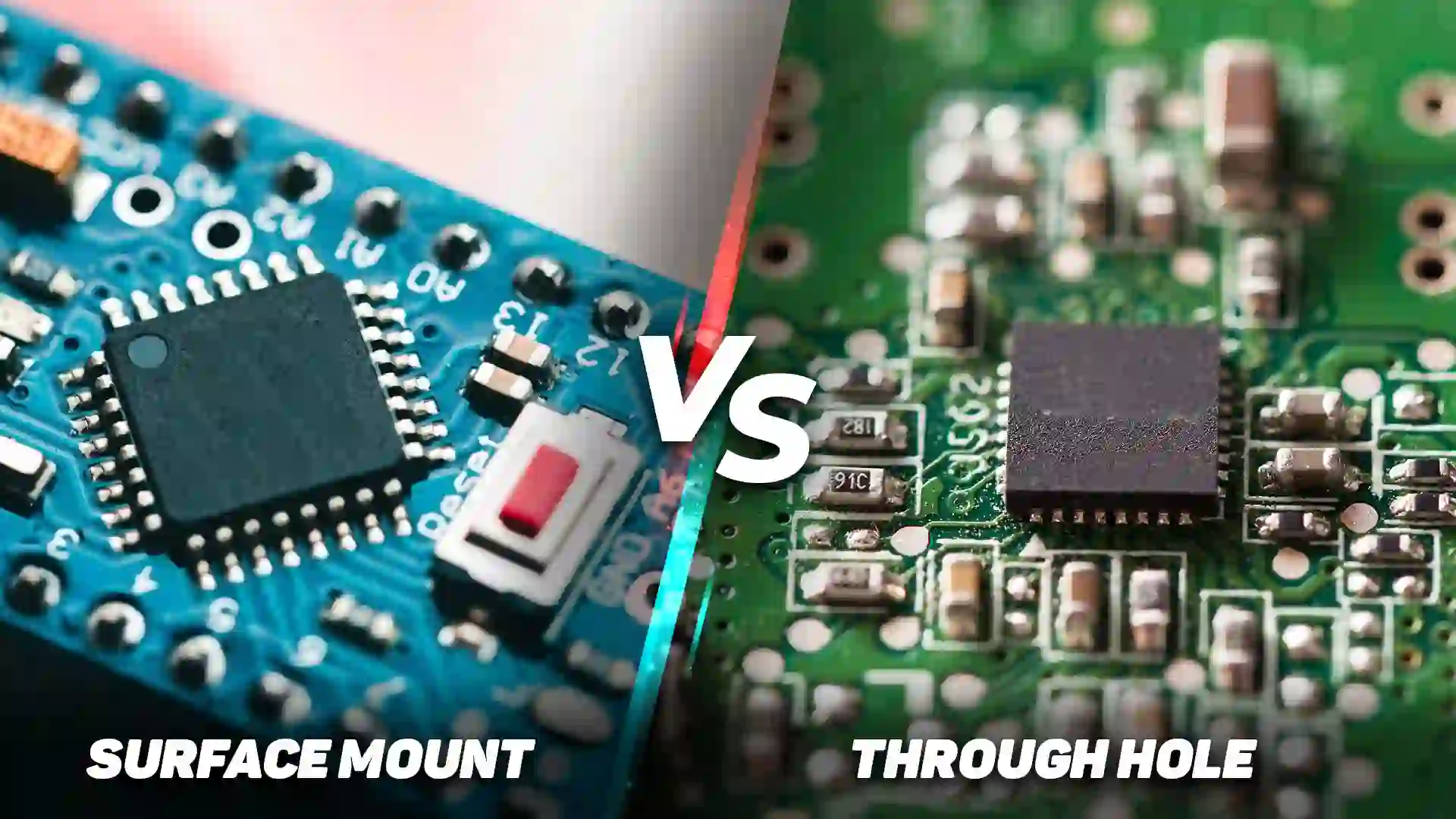
Through-Hole Mounting
Through-hole connectors have pins that pass through holes in the PCB and are soldered on the opposite side. This method offers strong mechanical stability, making it ideal for applications subject to vibration or stress. However, it takes up more space and is less suited for high-density designs. Typical current ratings for through-hole connectors range from 1A to 20A, depending on the pin size.
Surface Mount Technology (SMT)
Surface mount connectors are soldered directly onto the PCB surface, saving space and allowing for automated assembly. They’re perfect for compact, high-density designs like those in mobile devices. However, they may not withstand as much mechanical stress as through-hole options. SMT connectors often support currents up to 5A and are used for signal and low-power connections.
Press-Fit Mounting
Press-fit connectors use pins that are pressed into plated-through holes on the PCB, eliminating the need for soldering. This method is reliable for automotive and industrial applications where thermal cycling could weaken solder joints. Press-fit connectors can handle currents up to 30A or more, depending on the design.
Panel Mount and Cable Mount
Some connectors aren’t directly mounted on the PCB but are attached to a panel or cable that interfaces with the board. These are useful for external connections, such as power inputs or user interfaces. Panel mount connectors often support higher currents (10A to 50A) and voltages (up to 600V) for robust applications.
Connector Reliability Considerations for Long-Term Performance
Ensuring the longevity and reliability of your PCB design hinges on addressing connector reliability considerations. A connector that fails prematurely can disrupt the entire system, leading to downtime or safety issues. Here are key factors to evaluate:
Environmental Conditions
Consider the environment where your device will operate. Temperature, humidity, and exposure to dust or chemicals can degrade connector performance. For example:
- High-temperature environments (above 85°C) require connectors with heat-resistant materials like polyamide or LCP (liquid crystal polymer).
- Humid or corrosive settings call for connectors with gold-plated contacts to prevent oxidation.
Look for connectors with an IP (Ingress Protection) rating if dust or moisture is a concern. An IP67-rated connector, for instance, offers complete protection against dust and can withstand temporary immersion in water.
Mechanical Durability
Connectors in applications with frequent mating and unmating need to withstand wear and tear. Check the mating cycle rating, which indicates how many times a connector can be connected and disconnected before failure. A typical USB connector might be rated for 1,500 cycles, while industrial connectors can exceed 10,000 cycles.
Contact Resistance and Signal Integrity
Low contact resistance ensures minimal power loss and heat generation. High-quality connectors often have contact resistance below 20 milliohms. For high-speed data applications, choose connectors designed to minimize crosstalk and maintain signal integrity at speeds up to 10 Gbps or higher.
Vibration and Shock Resistance
In automotive or aerospace applications, connectors must resist vibration and shock. Look for designs with secure locking mechanisms or reinforced housings. Some connectors are tested to withstand vibrations up to 10G, ensuring reliability in harsh conditions.
How to Choose the Right PCB Connector for Your Project
With so many options and specifications to consider, selecting the right connector can feel overwhelming. Follow this step-by-step approach to simplify the process:
- Define Your Electrical Needs: Determine the current and voltage requirements of your circuit. Ensure the connector’s ratings exceed your system’s maximum values by at least 25% for safety.
- Identify the Connection Type: Decide whether you need board-to-board, wire-to-board, or another type based on your design layout.
- Consider Space Constraints: Choose a mounting option (through-hole, SMT, etc.) that fits your PCB layout and assembly process.
- Evaluate Environmental Factors: Match the connector’s material and protection ratings to the operating conditions of your device.
- Prioritize Reliability: Opt for connectors with proven durability, low contact resistance, and suitability for your application’s mechanical demands.
By systematically addressing these factors, you can narrow down your choices and select a connector that balances performance, cost, and reliability.
Common Mistakes to Avoid When Selecting PCB Connectors
Even experienced engineers can overlook critical details when choosing connectors. Here are some pitfalls to watch out for:
- Underestimating Current or Voltage Needs: Always account for peak loads, not just average values, to prevent overheating or failure.
- Ignoring Mating Cycles: Choosing a connector with a low mating cycle rating for a frequently disconnected system will lead to early wear.
- Overlooking Size Constraints: A connector that doesn’t fit your PCB layout can force costly redesigns.
- Neglecting Environmental Impact: Failing to consider temperature, humidity, or vibration can result in premature connector failure.
Conclusion: Building Reliable PCB Designs with the Right Connectors
Choosing the right PCB connector for your project is a fundamental step in creating a reliable, high-performing electronic system. By understanding the types of PCB connectors, evaluating connector current rating and connector voltage rating, exploring connector mounting options, and addressing connector reliability considerations, you can confidently design a PCB that meets your project’s needs. At ALLPCB, we’re dedicated to supporting your design journey with resources and expertise to help you succeed. Use this guide as your roadmap to select connectors that enhance both functionality and durability in your next project.


