 ALLPCB


When it comes to PCB assembly, identifying the most critical and vulnerable components is essential for ensuring the reliability and performance of electronic devices. These components often play a pivotal role in the functionality of the circuit, and any failure can lead to costly repairs or system downtime. In this comprehensive guide, we’ll dive deep into the key components that demand extra attention during PCB assembly, focusing on thru-hole assembly, mixed technologies, component list updates, and components spacing. Whether you're an engineer or a designer, this post will provide actionable insights to help you build robust and efficient printed circuit boards.
Understanding PCB Assembly and Its Challenges
PCB assembly, often referred to as PCBA, is the process of mounting electronic components onto a printed circuit board to create a functional circuit. This process can involve various techniques, such as surface-mount technology (SMT), thru-hole assembly, or mixed technologies that combine both. Each method has its own set of critical components and vulnerabilities that can impact the final product's quality.
The main challenges in PCB assembly include ensuring proper component placement, maintaining adequate spacing, and protecting vulnerable parts from physical or thermal stress. By understanding these challenges, you can mitigate risks and improve the durability of your boards.
Critical Components in PCB Assembly
Certain components are deemed critical in PCB assembly due to their role in the circuit's operation or their susceptibility to damage. Below, we explore the most important ones:
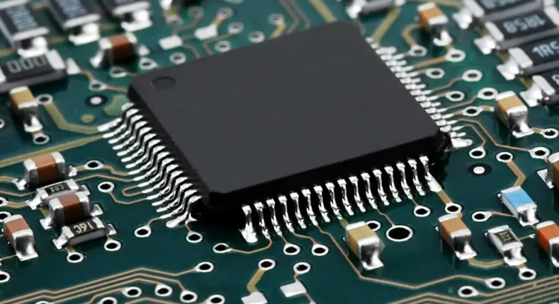
1. Microcontrollers and ICs
Microcontrollers and integrated circuits (ICs) are the heart of most electronic systems. These components process signals and control other parts of the circuit. However, they are highly sensitive to electrostatic discharge (ESD) and thermal stress during soldering. A single mishap can render an IC unusable, leading to system failure.
To protect these components, use proper ESD handling procedures and ensure soldering temperatures do not exceed the manufacturer’s specifications, often around 260°C for lead-free soldering processes.
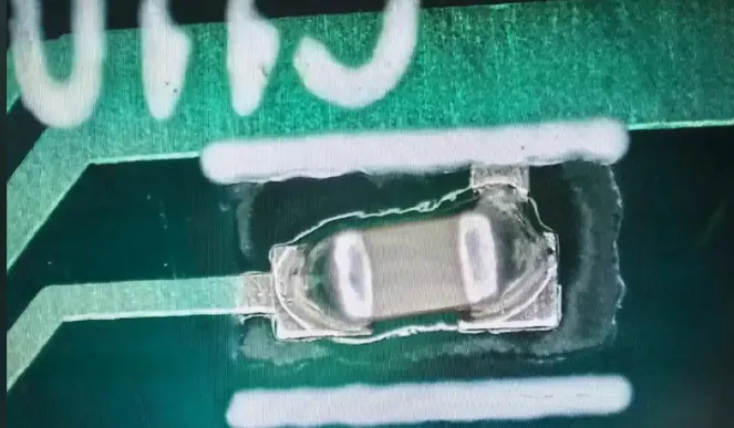
2. Capacitors and Resistors
Capacitors and resistors are fundamental to managing voltage and current in a circuit. While they are generally robust, incorrect polarity placement for capacitors or excessive heat can cause them to fail. Tantalum capacitors, for instance, are particularly vulnerable to reverse polarity, which can result in catastrophic failure or even explosions.
Always double-check the orientation of polarized components and adhere to recommended soldering profiles to avoid damage.
3. Connectors and Switches
Connectors and switches are critical for user interaction and system integration. However, they are prone to mechanical stress and wear over time. Poor soldering or misalignment during assembly can lead to intermittent connections or complete failure.
Ensure that connectors are securely mounted and that soldering joints are inspected for cracks or weak bonds.
Vulnerable Components in PCB Assembly
While critical components are vital to functionality, vulnerable components are those most likely to fail due to environmental factors, assembly errors, or design flaws. Here are the key ones to watch out for:
1. Fine-Pitch Components
Fine-pitch components, such as quad flat no-lead (QFN) packages, have closely spaced pins that make them prone to soldering defects like bridging or insufficient solder. These issues can lead to poor electrical connections and signal integrity problems.
To minimize risks, use precise pick-and-place machines and ensure reflow soldering profiles are optimized for fine-pitch parts, maintaining peak temperatures between 235°C and 250°C for lead-free solder.
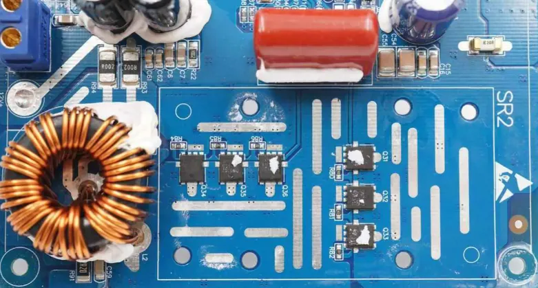
2. High-Power Components
Components like power transistors and voltage regulators handle high currents and voltages, making them susceptible to overheating. Without proper heat dissipation through heat sinks or thermal vias, these parts can degrade quickly.
Design your PCB with adequate thermal management, such as placing thermal vias under high-power components to transfer heat to the opposite side of the board.
3. Electrolytic Capacitors
Electrolytic capacitors are notorious for their limited lifespan and sensitivity to temperature and voltage stress. Overheating during soldering or exposure to high operating temperatures (above 85°C) can cause them to leak or fail.
Choose capacitors with appropriate temperature ratings and ensure they are placed away from heat sources on the PCB.
Thru-Hole Assembly: Unique Challenges and Components
Thru-hole assembly involves inserting component leads through holes in the PCB and soldering them on the opposite side. While this method is less common today due to the dominance of SMT, it is still used for components requiring high mechanical strength, such as large connectors and electrolytic capacitors.
The critical components in thru-hole assembly include:
- Large Transformers: These are heavy and can stress the PCB if not properly secured, leading to cracked solder joints.
- Power Resistors: These handle significant power and can overheat if not soldered correctly, affecting nearby components.
Vulnerabilities in thru-hole assembly often stem from mechanical stress during insertion or wave soldering. Excessive force can damage the PCB holes or leads, while improper soldering temperatures (typically around 260°C to 300°C for wave soldering) can weaken joints.
To address these issues, use automated insertion machines to reduce mechanical stress and ensure soldering temperatures are within the recommended range for your components.
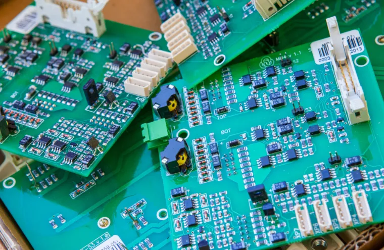
Mixed Technologies in PCB Assembly
Mixed technologies combine SMT and thru-hole assembly on the same board, often to balance performance and durability. For example, a board might use SMT for compact ICs and thru-hole for heavy-duty connectors. However, this approach introduces unique challenges.
Critical components in mixed technologies include:
- SMT ICs: These are vulnerable to thermal stress during wave soldering for thru-hole parts if not properly protected.
- Thru-Hole Connectors: These can cause mechanical stress on the board if not aligned with SMT components.
Vulnerabilities often arise from the differing soldering processes. SMT components typically undergo reflow soldering at 235°C to 250°C, while thru-hole components may require wave soldering at higher temperatures. This mismatch can damage sensitive parts.
To mitigate risks, consider using selective soldering for thru-hole components or applying thermal shields to protect SMT parts during wave soldering.
Component List Update: Keeping Your Designs Current
Updating your component list is a crucial step in PCB assembly to avoid obsolescence and ensure compatibility with modern manufacturing processes. Outdated components may no longer be available or may not meet current performance standards, leading to delays or redesigns.
Focus on the following when updating your component list:
- Check for Obsolescence: Verify if any critical components, such as specific ICs, have been discontinued by manufacturers.
- Review Specifications: Ensure components meet the latest voltage, current, and thermal requirements for your design.
- Source Alternatives: Identify drop-in replacements for obsolete parts with similar footprints and electrical characteristics.
Regularly updating your component list, ideally every 6 to 12 months, helps prevent supply chain disruptions and ensures your designs remain manufacturable.
Components Spacing: Guidelines for Reliable Designs
Proper components spacing is vital for preventing electrical interference, ensuring manufacturability, and facilitating repairs. Inadequate spacing can lead to issues like crosstalk, overheating, or soldering defects.
Here are some general spacing guidelines for PCB assembly:
- Component-to-Component Spacing: Maintain at least 40 mils (1 mm) between components to avoid soldering issues and ensure accessibility for rework.
- Component-to-Board Edge: Keep components at least 100 mils (2.54 mm) from the board edge to prevent damage during handling or mounting.
- High-Voltage Components: For components operating above 50V, increase spacing to at least 200 mils (5 mm) to prevent arcing.
For mixed technologies, ensure additional spacing between SMT and thru-hole components to accommodate different soldering processes and reduce thermal stress. Using design software with built-in design rule checks (DRC) can help enforce these spacing rules during layout.
Best Practices for Protecting Critical and Vulnerable Components
To ensure the longevity and reliability of your PCB assembly, follow these best practices:
- Use Automated Assembly: Automated pick-and-place and soldering machines reduce human error and ensure consistent results, especially for fine-pitch components.
- Implement Thermal Management: Add heat sinks, thermal vias, or copper pours to dissipate heat from high-power components.
- Conduct Thorough Testing: Perform in-circuit testing (ICT) and functional testing after assembly to identify defects in critical components early.
- Follow IPC Standards: Adhere to industry standards like IPC-A-610 for acceptable assembly quality, ensuring robust soldering and component placement.
Conclusion
In PCB assembly, understanding the most critical and vulnerable components is key to designing reliable and efficient electronic systems. From microcontrollers and fine-pitch ICs to electrolytic capacitors and high-power transistors, each part requires careful handling and precise assembly techniques. Whether you’re working with thru-hole assembly, mixed technologies, or updating your component list, attention to detail in components spacing and thermal management can make all the difference.
By following the guidelines and best practices outlined in this post, you can minimize risks, enhance performance, and ensure your PCB designs stand the test of time. Stay proactive in updating your knowledge and processes to keep pace with evolving technologies and manufacturing standards.


