ALLPCB


Power cable components and their functions
Power cable systems transmit electrical energy and typically include the following components, each serving a specific function:
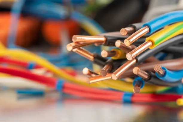
- Conductor: The conductor is the main transmission medium and carries current. Conductors are usually made of copper or aluminum and may be a single solid conductor or multiple stranded wires. Selection of the conductor considers resistance, conductivity, and mechanical strength.
- Insulation: The insulation surrounds the conductor to provide electrical isolation and prevent contact between the conductor and the surrounding environment. Common insulation materials include polyethylene (PE), cross-linked polyethylene (XLPE), and various rubbers. Insulation thickness and material are chosen according to the voltage level and operating conditions.
- Sheath: The sheath covers the insulation and protects it from mechanical damage, chemical corrosion, and moisture. Sheaths are typically made from weather-resistant and chemically resistant materials such as polyvinyl chloride (PVC) or polyethylene (PE). Sheath thickness and material are selected based on the operating environment and application requirements.
- Joint: Joints connect two cable sections and provide a continuous, reliable, and safe electrical connection between cable segments or other equipment. Joints are typically insulated using insulating sleeves and fillers to maintain insulation performance at the joint.
- Termination: Terminations connect the cable to end equipment such as transformers or motors. Their purpose is to ensure reliable electrical connection and insulation, commonly implemented using insulating sleeves and crimping techniques.
These components work together to form a complete power cable system for energy transmission and distribution. Cable structure and component choices vary with voltage level, current capacity, environment, and application. Proper design and selection are important to ensure efficiency, stability, and safety.
Common faults in power cable systems
Common faults in power cable systems include:
- Mechanical damage: The most frequent fault type, caused by external forces acting on the cable. Damage can be minor and not cause immediate failure, but may develop into faults months or years later.
- Moisture ingress in insulation: Long-term buried cables with inadequate waterproofing may suffer reduced insulation performance and subsequent faults.
- Insulation aging: Insulation degrades over time due to environmental stress. Cables used in harsh conditions age faster, and insulation aging-related faults are common in long-operated systems.
- Poor design or manufacturing quality: Faults caused by low-quality cables or construction shortcuts that prevent the cable from meeting design standards.
- Flashover faults: When voltage rises into a certain range or remains elevated, insulation can be instantly breached, causing a flashover.
- Open conductors in one or more phases: During continuity testing, if phase conductors meet insulation resistance specifications but continuity is missing for one or more phases, it indicates an open conductor in that phase.
- One- or two-phase grounding in three-core cables: If one or two cores test discontinuous with an insulation tester and subsequent insulation-to-ground resistance is much lower between cores than normal, this may indicate a high-resistance grounding fault (resistance above 1000 ohms) or a low-resistance grounding fault (resistance below that level).
- Three-phase conductor short circuit: Grounding resistance during a short circuit is used to classify three-phase short-circuit faults. Short-circuit faults are categorized as low-resistance or high-resistance; grounding resistance below 1000 ohms indicates a low-resistance short, while higher values indicate a high-resistance short.
These faults can arise from mechanical damage, overheating, excessive voltage load, poor design, or manufacturing defects.
Flashover faults versus insulation aging
Flashover faults and insulation aging are distinct issues, though they can be related.
Flashover faults typically result from localized breakdown of the dielectric due to partial discharges or arcing in high-voltage equipment. When arc currents are large enough, flashovers can cause sustained discharges, overvoltage, and other severe consequences. Manifestations include visible arcing or flashing on high-voltage equipment surfaces, dielectric breakdown and punctures in insulating media, damage or corrosion to components, equipment malfunction, and sudden voltage flicker or voltage drop in the power system.
Insulation aging refers to the gradual deterioration of insulating materials and structures over time due to electric field stress, temperature, mechanical forces, humidity, and environmental factors. Aging rate depends on insulation design, material, manufacturing quality, operating environment, voltage stress, and load conditions. Insulation aging ultimately leads to insulation failure and the inability of equipment to continue operating.
Although both affect electrical equipment, their causes and manifestations differ. Flashover can also be a consequence of insulation aging, since long-term aging may weaken insulation and make it susceptible to flashover under high voltage. Regular inspection and maintenance are therefore important to detect and address these issues and maintain power system stability.