ALLPCB


In the fast-evolving world of electronics, creating smaller, more powerful devices is a top priority. If you're looking to master small PCB design and high-density PCB layout, the key lies in optimizing component placement. This blog post dives deep into proven component placement strategies and miniaturization techniques to help you design compact, efficient, and reliable printed circuit boards (PCBs). We'll also cover thermal management for small PCBs to ensure your designs perform under pressure.
Whether you're an engineer working on wearable tech, IoT devices, or medical equipment, this guide offers practical tips and detailed insights to shrink your PCB size without sacrificing functionality. Let's explore how to achieve miniaturization while maintaining performance and reliability.
Why Miniaturization Matters in PCB Design
Miniaturization is more than just a trend; it's a necessity in modern electronics. From smartphones to smartwatches, consumers demand smaller, lighter devices packed with features. For engineers, this means fitting more components into less space using high-density PCB layout techniques. However, shrinking PCB form factors comes with challenges like signal interference, heat buildup, and manufacturing limitations.
Optimizing component placement is the foundation of successful small PCB design. Proper placement reduces noise, improves signal integrity, and helps manage heat dissipation. By mastering miniaturization techniques, you can create boards that are not only compact but also cost-effective and easy to manufacture.

Key Challenges in Small PCB Design
Before diving into solutions, it's important to understand the obstacles in small PCB design. These challenges directly impact how you approach component placement and layout:
- Space Constraints: Limited board area forces components to be packed tightly, increasing the risk of interference and crosstalk.
- Signal Integrity: Closer components can lead to higher electromagnetic interference (EMI), affecting performance. For high-speed signals, trace lengths must be minimized to maintain integrity, often requiring impedance control around 50 ohms for standard designs.
- Thermal Issues: High-density layouts generate more heat in a smaller area, risking component failure if not managed properly.
- Manufacturing Limits: Smaller components and tighter spacing demand advanced fabrication techniques, which can raise costs.
Addressing these challenges starts with strategic planning and the right component placement strategies. Let's break down the best practices for optimizing your design.
Component Placement Strategies for High-Density PCB Layout
Effective component placement is the cornerstone of a successful high-density PCB layout. Here are actionable strategies to ensure your design is both compact and functional:
1. Prioritize Critical Components First
Start by placing the most critical components, such as microcontrollers, power regulators, and high-speed connectors. These components often dictate the layout of traces and other parts. For instance, placing a microcontroller near the center of the board can minimize trace lengths for connected peripherals, reducing signal delays (often targeting speeds up to 1 GHz for modern designs).
Group related components together to create functional blocks. This approach simplifies routing and reduces the risk of interference in a small PCB design.
2. Optimize for Signal Flow
Arrange components to ensure a logical flow of signals across the board. High-speed signals should follow the shortest, most direct paths to avoid delays and maintain integrity. For differential pairs, keep traces parallel and equal in length to prevent timing issues, often maintaining a differential impedance of 100 ohms.
Avoid crossing high-speed traces with power or ground lines to minimize noise. If crossings are unavoidable, use vias or layer transitions carefully to maintain signal quality.

3. Use Layer Stacking for Miniaturization
In miniaturization techniques, stacking multiple layers is a powerful way to save space. High-density interconnect (HDI) technology allows for finer traces and smaller vias, enabling more components in a smaller footprint. For example, using buried vias (as a space-saving technique) can increase routing density by up to 30% compared to traditional through-hole vias.
Distribute power and ground planes across dedicated layers to reduce noise and improve thermal distribution. A typical 4-layer board might allocate the top and bottom for signals, with inner layers for power and ground.
4. Minimize Component Footprint
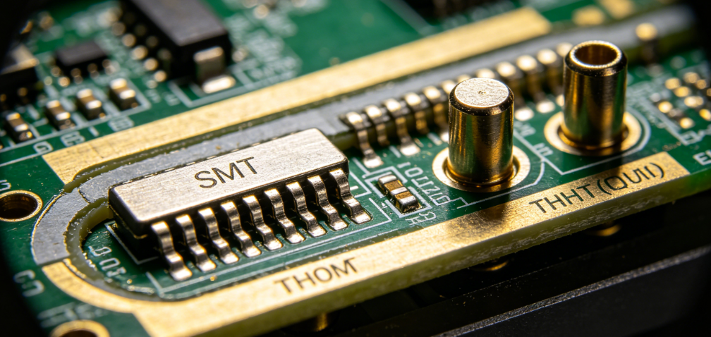
Choose smaller package sizes whenever possible, such as 0402 or 0201 for passives instead of larger 0805 components. Surface-mount devices (SMDs) are ideal for small PCB design as they take up less space than through-hole parts. Additionally, consider integrated circuits (ICs) with higher pin density, like QFN or BGA packages, to pack more functionality into a compact area.
Be mindful of manufacturing tolerances—components placed too close together (e.g., less than 0.1 mm spacing) may lead to assembly issues.
Miniaturization Techniques for Small PCB Form Factors
Beyond component placement, several miniaturization techniques can help you achieve smaller PCB sizes without compromising performance. Here are some advanced methods to consider:
1. Adopt High-Density Interconnect (HDI) Design
HDI technology is a game-changer for high-density PCB layout. It uses microvias, blind vias, and buried vias to increase routing density. Microvias, with diameters as small as 0.1 mm, allow for finer connections between layers, freeing up surface space for more components.
HDI also supports thinner boards, reducing overall device thickness. This is especially useful for applications like wearables, where every millimeter counts.
2. Integrate Passive Components
Embedding passive components like resistors and capacitors into the PCB substrate is an emerging trend in miniaturization techniques. This approach eliminates the need for surface-mounted parts, saving valuable board space. While this requires advanced manufacturing, it can reduce PCB size by up to 20% in some designs.
3. Utilize 3D Component Placement
In extremely tight spaces, consider stacking components vertically or using 3D packaging solutions. For example, chip-on-chip or package-on-package (PoP) configurations allow multiple ICs to be stacked, significantly reducing the board's footprint. This technique is common in mobile devices where space is at a premium.

Thermal Management for Small PCBs
One of the biggest challenges in small PCB design is managing heat. With components packed tightly in a high-density PCB layout, heat dissipation becomes critical to prevent failures. Here are effective strategies for thermal management in small PCBs:
1. Use Thermal Vias
Thermal vias are small holes filled with conductive material that transfer heat from hot components to a heat sink or ground plane. For high-power components like voltage regulators, place an array of thermal vias (e.g., 0.3 mm diameter, spaced 1 mm apart) directly beneath the component to improve heat dissipation.
2. Optimize Copper Pour and Planes
Increase the copper area around heat-generating components to act as a heat spreader. Dedicated ground planes on inner layers can also absorb and distribute heat evenly across the board. For example, a copper thickness of 2 oz/ft2 offers better thermal conductivity than the standard 1 oz/ft2.
3. Select Heat-Resistant Materials
Choose PCB substrates with high thermal conductivity, such as FR-4 with enhanced properties or metal-core PCBs for extreme cases. These materials help dissipate heat more effectively, protecting components in compact designs.
4. Strategic Component Spacing
Even in a small PCB design, avoid clustering heat-generating components together. Spread them across the board to prevent localized hot spots. If possible, place high-power components near the board's edges for better airflow or heat sink attachment.
Tools and Software for Optimizing Small PCB Layouts
Designing a high-density PCB layout requires the right tools to simulate, test, and refine your design. Modern PCB design software offers features like auto-placement, thermal analysis, and signal integrity checks to streamline the process.
Look for tools that support HDI design and provide real-time feedback on trace lengths and impedance. Many platforms also include libraries for small-footprint components, making it easier to select parts for miniaturization techniques. Additionally, simulation features can help you identify thermal hotspots and optimize thermal management for small PCBs before manufacturing.
Best Practices for Manufacturability in Small PCB Design
A well-optimized design is only valuable if it can be manufactured reliably. Keep these tips in mind to ensure your small PCB design is production-ready:
- Adhere to Design Rules: Follow the manufacturer's design rules for minimum trace widths, spacing, and via sizes. For HDI designs, trace widths as small as 3 mils (0.076 mm) may be possible with advanced fabrication.
- Test Before Production: Use design-for-manufacturability (DFM) checks to identify potential issues like insufficient clearances or unrouteable traces.
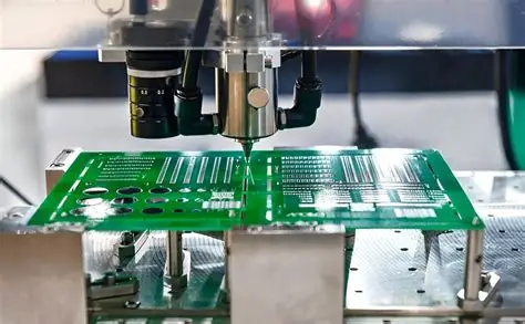
- Plan for Assembly: Ensure enough space for pick-and-place machines to handle tiny components, typically requiring at least 0.2 mm clearance around SMD pads.
Conclusion: Mastering Miniaturization for Future-Ready Designs
Miniaturization is a critical skill for any engineer working on modern electronics. By focusing on component placement strategies, leveraging miniaturization techniques, and prioritizing thermal management for small PCBs, you can create compact designs that meet the demands of today's market.
Start with a clear plan for your high-density PCB layout, prioritize signal integrity, and use advanced tools to refine your design. With the right approach, your small PCB design can achieve incredible performance in the tiniest form factors. Embrace these strategies to stay ahead in the race for smaller, smarter, and more efficient electronics.