 ALLPCB


If you're new to electronics and wondering what impedance testing is all about, you're in the right place. Impedance testing is a method used to measure how much a circuit resists the flow of alternating current (AC). It’s a key concept for understanding signal behavior in electronic designs, ensuring your circuits work efficiently without signal loss or distortion. In this guide, we'll break down impedance testing basics, explain what is impedance, dive into AC impedance explained, and walk you through impedance measurement for dummies with simple impedance testing circuits. Let’s get started with everything you need to know, step by step.
What Is Impedance? A Beginner-Friendly Explanation
Impedance might sound like a complex term, but it’s quite simple once you break it down. In the world of electronics, impedance is the total opposition a circuit offers to the flow of alternating current (AC). Unlike resistance, which only applies to direct current (DC) and is a straightforward measure of opposition, impedance includes both resistance and reactance. Reactance comes from components like capacitors and inductors, which behave differently with AC signals due to their ability to store and release energy.
To put it in numbers, impedance (Z) is often expressed in ohms (Ω) and can be calculated using the formula:
Z = √(R2 + (X_L - X_C)2)
Here, R is resistance, X_L is inductive reactance, and X_C is capacitive reactance. Don’t worry if this formula looks intimidating—we’ll explain how it works in practical terms later. For now, just know that impedance affects how signals travel through your circuit, impacting everything from audio systems to high-speed digital designs.
Related Reading: Understanding Impedance Calculators: Optimizing Signal Integrity in PCB Design
Why Impedance Testing Matters in Electronics
Impedance testing is critical because mismatched impedance can lead to signal reflections, power loss, and poor performance in your circuits. Imagine sending a signal through a cable to a speaker. If the impedance of the cable doesn’t match the speaker, part of the signal bounces back, causing distortion or reduced sound quality. In high-speed circuits, like those in modern computers, improper impedance can result in data errors or slower performance.
For example, in a typical audio system, speakers often have an impedance of 4 to 8 ohms. If your amplifier isn’t matched to this range, you might lose up to 50% of the power output, leading to weaker sound. In PCB design, controlled impedance is vital for traces carrying high-frequency signals, often requiring values like 50 ohms or 75 ohms to prevent signal degradation.
By understanding and testing impedance, you can ensure your designs deliver signals efficiently, whether you’re working on a simple hobby project or a complex industrial system.
AC Impedance Explained: How It Differs from DC Resistance
One of the biggest hurdles for beginners is understanding the difference between AC impedance and DC resistance. Resistance is a static value—it’s the opposition to current flow in a DC circuit, and it’s measured with a simple multimeter. Impedance, on the other hand, is dynamic and applies to AC circuits where the current changes direction constantly.
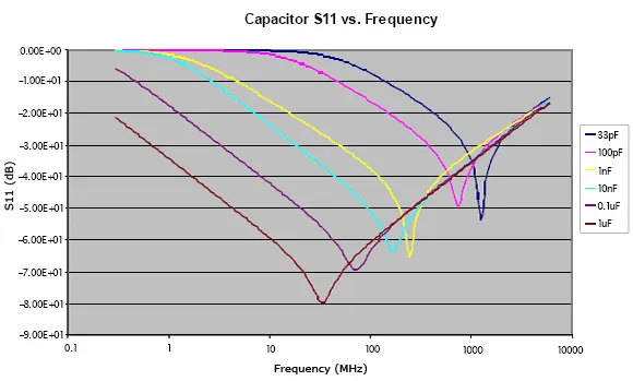
In an AC circuit, components like capacitors and inductors introduce reactance, which depends on the frequency of the signal. For instance, a capacitor’s impedance decreases as frequency increases, while an inductor’s impedance increases with frequency. This means a circuit’s impedance can vary depending on whether the signal is at 60 Hz (like household power) or 1 GHz (like wireless communications).
Here’s a quick example: A capacitor with a value of 1 μF has an impedance of about 2.65 kΩ at 60 Hz, but at 1 MHz, its impedance drops to just 0.16 Ω. This frequency-dependent behavior is why AC impedance testing is so important for designing circuits that handle varying signal speeds.
Impedance Measurement for Dummies: Tools and Techniques
Now that you understand what impedance is, let’s talk about how to measure it. Impedance measurement doesn’t have to be complicated, even for beginners. With the right tools and techniques, you can get accurate readings to ensure your circuits are performing as expected.
Tools You’ll Need
- Multimeter with AC Mode: For basic measurements, some multimeters can measure impedance at specific frequencies.
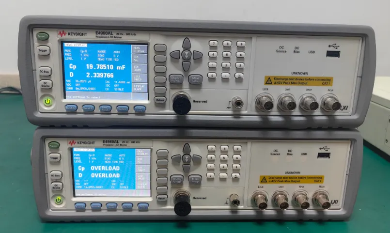
- LCR Meter: This is a more specialized tool that measures inductance (L), capacitance (C), and resistance (R), allowing you to calculate impedance.
- Oscilloscope and Signal Generator: For advanced testing, these tools help you analyze signal behavior across different frequencies.
- Impedance Analyzer: A professional tool for precise measurements, often used in high-frequency or complex circuit designs.
Basic Steps for Impedance Measurement
- Prepare Your Circuit: Disconnect power and ensure the circuit is safe to test. Identify the component or section you want to measure.
- Select the Right Tool: For simple components like resistors or capacitors, an LCR meter works best. For full circuits, you might need an oscilloscope setup.
- Set the Frequency: If you’re testing with AC, choose the frequency relevant to your application (e.g., 1 kHz for audio circuits).
- Take the Measurement: Connect the probes or test leads to the circuit and record the impedance value displayed.
- Analyze Results: Compare the measured impedance to the expected value for your design to identify mismatches or issues.
Simple Impedance Testing Circuits for Beginners
Let’s put theory into practice with a couple of easy circuits you can build to understand impedance testing. These hands-on examples will help solidify your knowledge and give you practical experience.
Circuit 1: Basic RC Circuit
An RC circuit (resistor and capacitor in series) is a great starting point for learning about impedance. Here’s how to build and test it:
- Components: 1 kΩ resistor, 1 μF capacitor, breadboard, wires, and a signal generator.
- Setup: Connect the resistor and capacitor in series. Attach the signal generator across the circuit.
- Test: Set the signal generator to 1 kHz and use an oscilloscope to measure the voltage across the capacitor. Calculate impedance using the formula Z = √(R2 + X_C2), where X_C = 1/(2πfC). At 1 kHz, X_C is about 159 Ω, so Z is roughly 1013 Ω.
This circuit shows how impedance combines resistance and capacitive reactance, and you’ll see how the signal behaves differently across the components.
Circuit 2: RL Circuit
An RL circuit (resistor and inductor) demonstrates inductive reactance. Here’s the setup:
- Components: 1 kΩ resistor, 10 mH inductor, breadboard, wires, and a signal generator.
- Setup: Connect the resistor and inductor in series. Attach the signal generator across the circuit.
- Test: Set the frequency to 1 kHz. Calculate impedance using Z = √(R2 + X_L2), where X_L = 2πfL. At 1 kHz, X_L is about 62.8 Ω, so Z is roughly 1002 Ω.
This setup helps you see how inductors oppose changes in current, affecting signal behavior at different frequencies.
Understanding Signal Behavior Through Impedance Testing
Impedance directly impacts how signals behave in a circuit. By testing impedance, you can predict and troubleshoot issues like signal loss, distortion, or delay. Here are a few key ways impedance affects signal behavior:
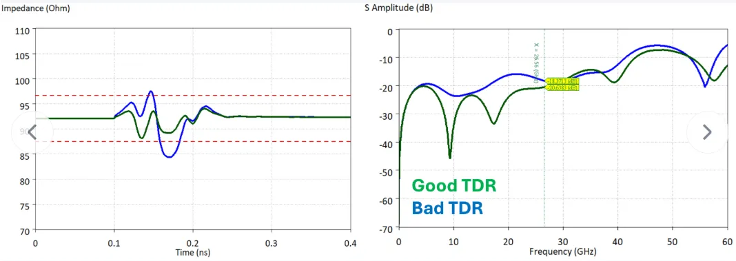
- Signal Reflection: When impedance isn’t matched between components (e.g., a 50-ohm trace connected to a 75-ohm load), part of the signal reflects back, causing noise or data errors. This is common in high-speed digital circuits where signal integrity is crucial.
- Power Transfer: Maximum power transfer happens when the source and load impedance are matched. For instance, in RF circuits, a mismatch can reduce efficiency by 20-30%, wasting energy.
- Frequency Response: Impedance changes with frequency, as we saw with capacitors and inductors. This affects how well a circuit filters or amplifies certain frequencies, which is vital for audio or communication systems.
By regularly testing impedance during design and prototyping, you can fine-tune your circuits to handle signals effectively, ensuring reliable performance.
Related Reading: PCB Impedance Testing: Why It Matters for Signal Integrity
Common Mistakes to Avoid in Impedance Testing
As a beginner, it’s easy to make mistakes when testing impedance. Here are some pitfalls to watch out for:
- Ignoring Frequency: Always test at the frequency your circuit will operate at. A measurement at 1 kHz won’t help if your design runs at 100 MHz.
- Using the Wrong Tool: A basic multimeter might not give accurate impedance readings for complex circuits. Invest in an LCR meter or oscilloscope for better results.
- Neglecting Parasitic Effects: Real-world components have parasitic capacitance or inductance that can skew measurements. Account for these in high-precision designs.
By being mindful of these issues, you’ll get more accurate data and avoid costly redesigns.
Tips for Effective Impedance Testing in PCB Design
For those working on printed circuit boards, impedance control is especially important. High-speed signals on a PCB require precise impedance matching to prevent signal integrity issues. Here are some practical tips:
- Design with Impedance in Mind: Use simulation tools during the design phase to calculate trace impedance, often targeting 50 ohms for RF or high-speed digital signals.
- Test During Prototyping: Measure impedance on prototype boards to confirm your design matches the intended values.
- Work with Reliable Manufacturers: Partner with a trusted PCB provider to ensure materials and manufacturing processes support controlled impedance.
Conclusion: Mastering Impedance Testing Basics
Impedance testing might seem daunting at first, but with the right knowledge and tools, it becomes a straightforward process. By understanding what is impedance, diving into AC impedance explained, and practicing with simple impedance testing circuits, you can ensure your circuits handle signals effectively. Whether you’re a hobbyist or an aspiring engineer, mastering impedance measurement for dummies will help you build better, more reliable designs.
Start small with basic circuits and measurements, then scale up as you gain confidence. With the tips and techniques covered in this guide, you’re well on your way to tackling impedance testing basics and improving signal behavior in your projects. Keep experimenting, keep learning, and watch your electronics skills grow!


