ALLPCB


Overview
This article describes how to pair energy-measurement ICs with current sensors to provide fault diagnosis, detection, isolation, and restoration for single-phase and three-phase designs in smart grid deployments.
Current and voltage sensors used in smart meters are relatively simple to implement, but converting their outputs into useful, complex data is challenging. Modern smart meters require substantial data to be reported back to the utility network, whether via local aggregators or central offices.
Smart meters must accurately determine active energy (kWh), apparent energy (kVA), reactive energy (kVAR), RMS values, and support power-quality and energy-monitoring applications. These requirements typically need multiple channels to capture data, which historically led to large and expensive metering systems.
Integrating sensor interfaces and on-board processing to capture and process sensor data effectively within the meter is a key development challenge.
Multichannel Current Capture
The ADE7816 is a high-precision, multichannel metering IC capable of measuring one voltage channel and up to six current channels. It measures line voltage and currents and computes active and reactive energy as well as instantaneous RMS voltage and current. The device integrates seven sigma-delta ADCs and a high-precision energy-measurement core. Six current inputs allow simultaneous measurements of multiple loads, capturing different measurements from a range of sensors and determining active, apparent, and reactive energy at any time. That data can be reported back to the utility network to optimize power delivery and form efficient feedback loops.
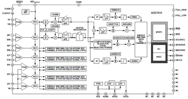
Figure 1: ADE7816 meter sensor interface combining one voltage channel with six current channels.
The voltage channel and six current channels provide a full signal path for wide-range measurements. Each input supports flexible gain stages suitable for current transformers (CTs). Six on-chip digital integrators allow the use of Rogowski coil sensors. Each channel can be configured for either a coil or a CT depending on system and phase requirements.
Rogowski Coils
A Rogowski coil is a low-cost sensor that uses a helical coil around an air core to measure AC current or fast current pulses. One lead of the coil is routed back through the center so both terminals are at the same end. The coil is wrapped around a straight conductor to measure current. Because the induced voltage is proportional to the rate of change of current (di/dt), the coil output is connected to the ADE7816 integrator to provide a current-proportional output.
Each analog input pin requires a simple RC anti-alias filter at the input to prevent aliasing of frequency components above half the ADC sampling rate. A corner frequency of 5 kHz is recommended to provide sufficient attenuation at the 1.024 MHz sampling rate. A single RC pole typically yields about -20 dB per decade attenuation, which is usually sufficient to remove aliasing. However, di/dt sensors such as Rogowski coils provide +20 dB per decade gain, which can offset the low-pass filter attenuation. When using di/dt sensors, an additional pole is required. A simple approach is to cascade an additional RC filter to achieve about -40 dB per decade attenuation.
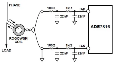
Figure 2: Anti-aliasing for Rogowski coils with the ADE7816.
Registers and Interfaces
The ADE7816 provides integrated instrument registers accessible via SPI or I2C. A dedicated high-speed data-capture (HSDC) port works with I2C to provide access to real-time ADC output data. Two external interrupt pins expose power-quality information such as overcurrent, overvoltage, peaks, and sags. The IRQ0 and IRQ1 interrupt lines are accessible through the active-energy signal path (see Figure 3).
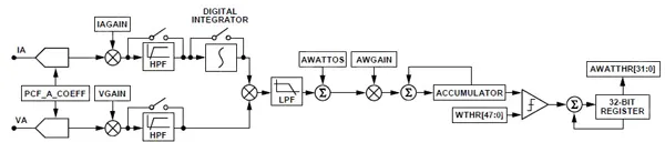
Figure 3: Active-energy signal path inside the ADE7816.
Power and Startup
In high-voltage environments such as meters, power supply design is a critical consideration. The ADE7816 requires a 3.3 V DC input between VDD and AGND/DGND. The PULL_HIGH and PULL_LOW pins must be tied to 3.3 V and AGND respectively.
The ADE7816 contains an on-chip power monitor for VDD. If the voltage on VDD is below 2 V ±10%, the chip remains invalid. After VDD rises above the threshold, the power monitor holds the ADE7816 in an invalid state for an additional 26 ms to allow VDD to reach the minimum rated operating voltage. When the minimum operating voltage is met and the PULL_HIGH and PULL_LOW pins are connected to VDD and AGND, internal circuits are enabled. The full startup process completes in approximately 40 ms.
When startup is complete and the ADE7816 is ready to receive communication from a microcontroller, the RSTDONE flag in the STATUS1 register indicates readiness. The IRQ1 pin triggers an external interrupt. RSTDONE is enabled by default and cannot be disabled, so the external interrupt always occurs at the end of power-up or after a hardware or software reset.
Microcontrollers should use the RSTDONE interrupt to control the initial communication with the ADE7816. If interrupts are not used, a timeout may be implemented; however, because the startup sequence can vary with part and temperature, a timeout of at least 100 ms is recommended. RSTDONE provides the most time-efficient method to detect completion of the startup sequence.
The AVDD and DVDD output pins provide access to on-chip analog and digital LDOs. When the ADE7816 is fully powered, these pins supply 2.5 V. If the internal reference is used, the REFIN/OUT pin outputs 1.2 V.
After startup, all registers default to their reset values and the I2C port is available for communication. For energy and RMS computations, the on-chip DSP must be powered after configuration registers are set. Enable the DSP by setting the RUN register (address 0xE228) to 0x0001.
Reference and Calibration
The REFIN/OUT nominal reference voltage is 1.2 V ±0.075%. The REFIN/OUT pin can be driven by an external 1.2 V reference if required. If CONFIG2 bit 0 (EXTREFEN) is cleared (default), the ADE7816 uses the internal reference. If that bit is set, an external reference is used.
The internal reference has a small temperature drift; see the device specifications for temperature-coefficient details in ppm/°C. Drift varies by part. Because the reference voltage is used by all ADCs, any drift in the reference causes a proportional impact on meter accuracy, effectively doubling the effect on measured values.
Reset Mechanisms
To perform a hardware reset, assert the RESET pin low for at least 10 μs. When RESET returns high, all registers restore to default values. The end of the reset is signaled by asserting the IRQ1 interrupt pin low and setting bit 15 (RSTDONE) in the STATUS1 register to 1. RSTDONE is 0 during conversion and becomes 1 when conversion completes.
Software reset is controlled via CONFIG register bit 7 (SWRST). If bit 7 is set, the ADE7816 enters a software reset and internal registers are set to default values except for CONFIG2, which retains its current value. If a lock procedure previously selected the serial port (I2C or SPI), that selection is preserved. When software reset completes, CONFIG bit 7 clears, IRQ1 is driven low, and STATUS1 bit 15 (RSTDONE) is set to 1. RSTDONE transitions from 0 to 1 as the reset completes.
Designs should include both software and hardware reset capability.
Evaluation Kit
The ADE7816 evaluation kit includes a board for silicon evaluation. The board contains the ADE7816 metering IC, associated filtering and isolation to allow high-voltage inputs, and a microcontroller that manages communications between a PC and the ADE7816 via the board USB connector.
The evaluation board requires an external 3.3 V DC supply applied at P9 to power the non-isolated side of the circuit, including the ADE7816. By default, USB provides power to the isolated side, including the microcontroller. If using an external isolated-side supply, apply it at P12 and move jumper JP24 to the 1-2 position.
Voltage Channel
The voltage channel input is available at P6. The evaluation board is designed for direct connection to a line-voltage source and includes a resistor divider to reduce the input voltage. The default voltage-channel configuration is shown in Figure 6a.
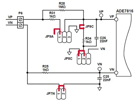
Figure 6a: Typical voltage-channel configuration.
The maximum signal level at VP relative to VN is 0.5 V peak. Modify the resistor divider network (R28 and R34 on the evaluation board) to accommodate other input levels.
Current Channels
The ADE7816 includes six single-ended current channels that can interface to CTs or Rogowski coils. The sensor output for current channel A is applied at P1. Like the voltage channel, the maximum input for all current inputs is 0.5 V peak. Figure 6b shows a typical configuration using a CT.
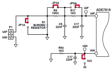
Figure 6b: Typical current channel A configuration with a current transformer.
When using a Rogowski coil, no burden resistor is required. A second-stage anti-aliasing filter is recommended and can be enabled via JP3A. Because the differential output of a Rogowski coil can offset a single-pole filter, the second stage is needed to achieve the required attenuation, as shown in Figure 6c.
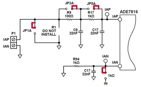
Figure 6c: Typical current channel A configuration with a Rogowski coil.
Current channels B through F are configured similarly. Channels D, E, and F share a common neutral, so a single anti-alias filter on the neutral line services all three channels.
Three-Phase Metering
For three-phase metering, the ADE78xx family provides high-precision three-phase energy measurement with serial interfaces and three flexible pulse outputs. These devices integrate second-order sigma-delta ADCs, digital integrators, reference circuitry, and perform comprehensive signal processing for total (fundamental plus harmonics) active and reactive energy, apparent energy, and RMS calculations. Some parts support fundamental-only active and reactive energy measurement. A fixed-function digital signal processor executes the signal processing and stores its program in internal ROM.
The ADE7854, ADE7858, ADE7868, and ADE7878 are suitable for measuring active, reactive, and apparent power in a variety of three-phase configurations, such as three-wire and four-wire Y or delta services. The ADE78xx devices provide per-phase system calibration via RMS offset correction, phase calibration, and gain calibration. The CF1, CF2, and CF3 logic outputs offer selectable power information such as total active, reactive, and apparent power, the sum of current RMS values, or fundamental active and reactive power.
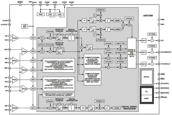
Figure 7: ADE7878 multi-phase meter interface.
All members of the family include waveform sampling registers that provide access to all ADC outputs. They also include power-quality measurement features such as short-term undervoltage or overvoltage detection, short-term high-current changes, line-voltage period measurement, and phase angle measurement between voltage and current. A high-speed data-capture port works with I2C to provide access to ADC outputs and real-time power information. The ADE7868 and ADE7878 include dedicated low-power modes to help ensure continuous energy accumulation during tamper events.
Part-number feature support varies across the ADE78xx family.
Conclusion
Current sensors themselves are relatively simple, but generating accurate meter data requires multiple capture and integration channels plus digital signal processing. For both single-phase and multi-phase systems, several highly integrated devices are available to determine key metering parameters, from active, apparent, and reactive energy to RMS and power-quality metrics. Evaluation boards for these single- and multi-phase designs provide a practical environment to develop and validate system implementations.