 ALLPCB


Traditional semi-anechoic chambers (SACs) and fully anechoic chambers (FACs) simulate open-area test sites and free-space environments, respectively. Recognized by international standards, they are widely used for EMC testing. Reverberation chamber (RVC) technology, also known as a mode-stirred chamber, employs a different testing approach. In recent years, the principles and methods of using reverberation chambers for EMC testing have seen significant research and development. As test requirements for equipment under test (EUT), particularly for automotive products, become more stringent, reverberation chamber technology has gained increasing attention.
Reverberation Chamber Operating Principles
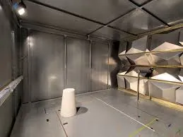
According to IEC 61000-4-21, a reverberation chamber is a specially designed shielded enclosure with a long reverberation time intended to create a diffuse electromagnetic field. A reverberation chamber consists of a shielded enclosure, a mechanical tuner or stirrer, antennas, a test system, and control software.
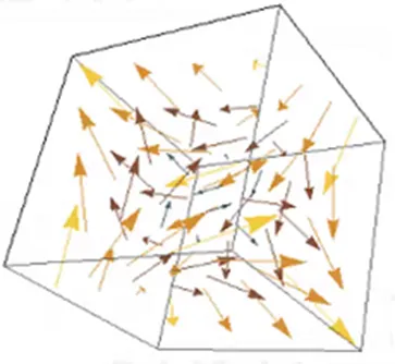
Traditional anechoic chambers are lined with RF absorbent material to absorb electromagnetic waves, minimizing reflections and multipath effects to improve field uniformity. In contrast, a reverberation chamber is a metallic shielded cavity with highly reflective walls. By rotating a tuner/stirrer, the boundary conditions of the electromagnetic field are continuously changed. This process generates a large number of randomly polarized electromagnetic wave signals, creating a constantly shifting field distribution. Over a statistical period, this forms a spatially uniform, isotropic, and randomly polarized electromagnetic environment that simulates real-world conditions.
Compared to traditional anechoic chambers, reverberation chambers have the following characteristics:
- Working Volume: A traditional anechoic chamber defines a working plane with a uniform field strength of a specific polarization. A reverberation chamber defines a three-dimensional working volume where electromagnetic waves have random polarization, and a statistically uniform field strength is achieved. For the same physical size, a reverberation chamber offers a larger test volume.
- Construction and Cost: Traditional anechoic chambers consist of a shielded room, ferrite tiles, and RF absorbent materials. A reverberation chamber consists of a shielded room and a stirrer, without the need for absorbers, resulting in lower construction costs.
- Field Strength Generation: Anechoic chambers use absorbent materials to absorb a large portion of the input energy to prevent reflections. A reverberation chamber utilizes multiple reflections, making it highly efficient. Therefore, a reverberation chamber can generate a higher test field strength with less input power.
- Operating Frequency: The lowest usable frequency (LUF) of a reverberation chamber is limited by its dimensions, while its high-frequency performance is generally not restricted.
- Test Time: Reverberation chamber testing typically requires longer test times compared to anechoic chambers.
Reverberation Chamber Test Procedure
A reverberation chamber test generally follows these steps:
Step 1: Empty Chamber Field Uniformity Calibration
This step verifies that the chamber's field uniformity meets standard requirements, determines the normalized electric field strength, and defines the working volume. It is performed once after the chamber is built or after significant modifications.
Step 2: Maximum Chamber Loading Verification
Building on Step 1, absorbent material is added to the chamber to simulate loading and re-verify field uniformity. This is also performed once after construction or major modifications.
Step 3: EUT Loading Pre-check
A "quick check" of the chamber's performance is done to confirm that the loading from the EUT is less than the maximum simulated loading. This step is performed for each new EUT.
Step 4: EUT Testing
The EUT is tested using the forward power levels recorded during the calibration phase.
Reverberation Chamber Test System
A complete reverberation chamber test system consists of the following main components:
1. Reverberation Chamber: Includes the enclosure, shielded door, stirrer, antennas, and field probes.
2. Test Equipment: Similar to systems for anechoic chambers, the test equipment includes:
- Signal generator to produce the required interference signal waveforms.
- Power amplifier to amplify the signal to the desired power level.
- Power meter to monitor forward and reverse power, determining the net power delivered into the chamber.
- Transmit antenna to introduce the interference signal into the chamber.
- Receive antenna to monitor the field strength during the test.
- Field probe for field strength verification within the working volume.
3. Test Software: Used to control the system for chamber validation and automated testing.
Complete EMS test systems integrate the necessary instruments and accessories for reverberation chamber testing. These systems can be configured according to international, national, or proprietary standards. Control software is used to manage the system and implement repeatable, fully automated test procedures.


