 ALLPCB


1. Introduction
There are many massage chairs on the market. Adding new features to differentiate products can introduce EMC issues. This case describes EMC fixes after replacing a basic handheld controller with a display.
2. Case study
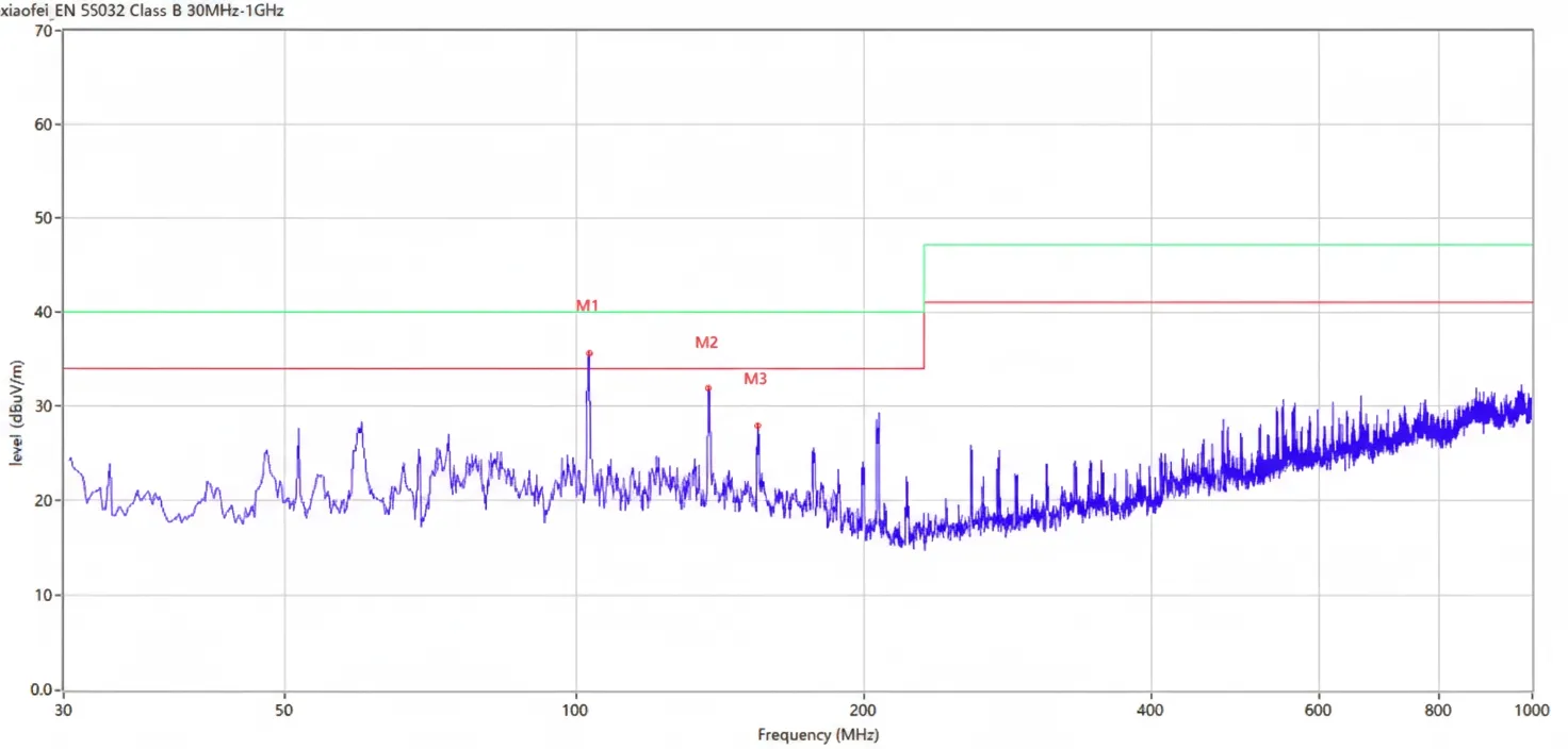
Initial test data were as follows:
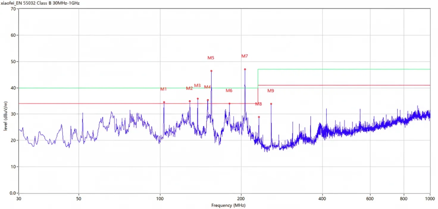
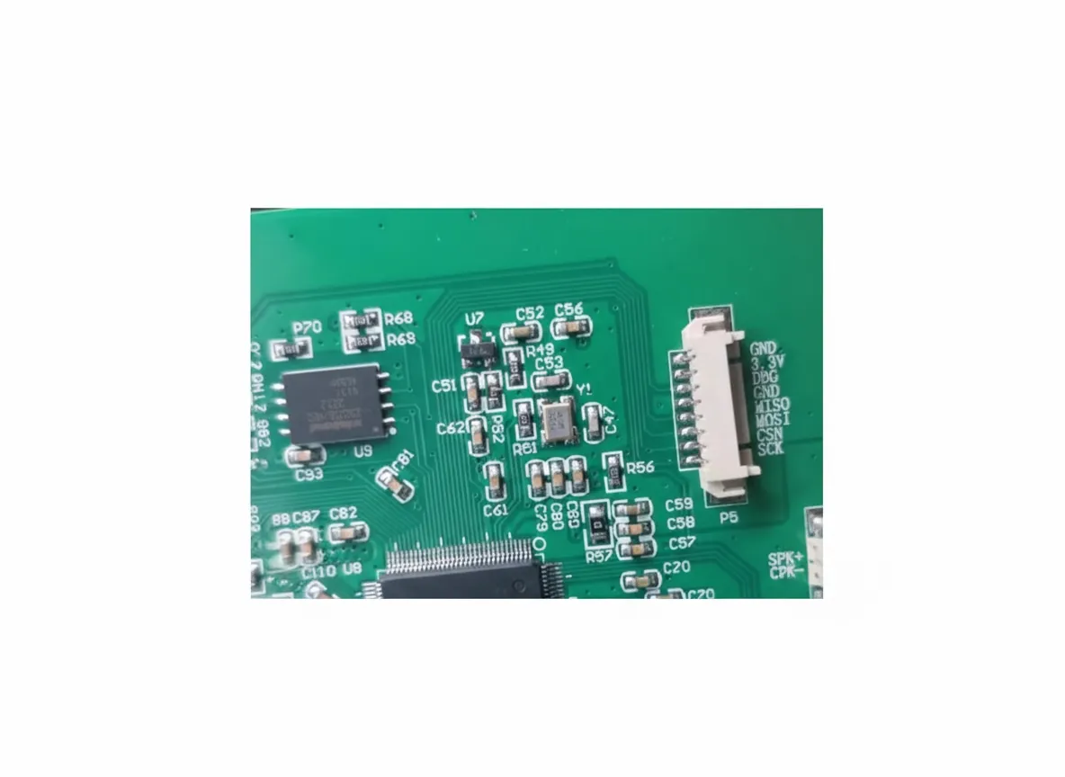
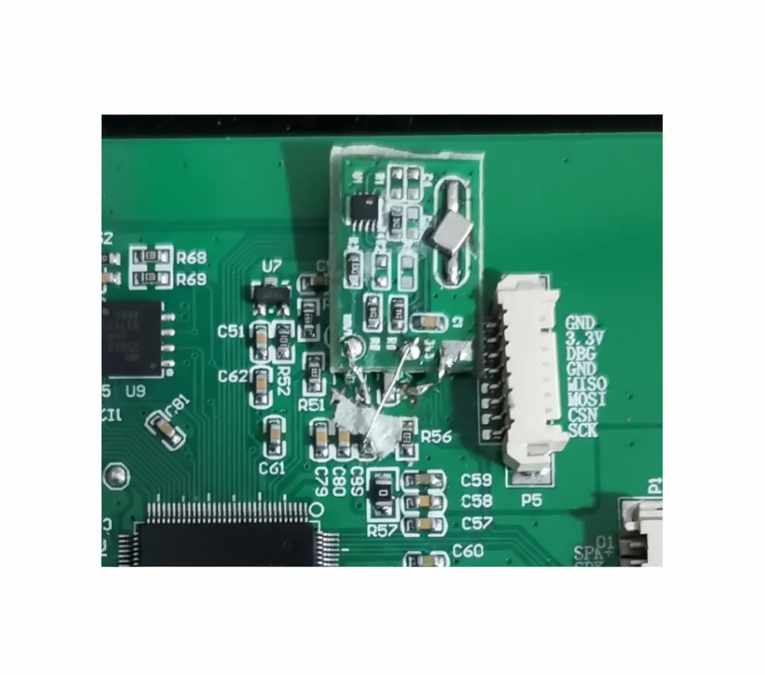
The first step after receiving the data was to analyze it. The data clearly showed a clock-related exceedance. After identifying the clock as the cause, we inspected the device PCB to understand functional modules before locating the noise source. We have handled many clock issues and have a three-step approach. First, add a spread-spectrum IC to the chip's main clock to spread the clock. The images below compare before and after; the circled area on the right is the spread-spectrum demo board.
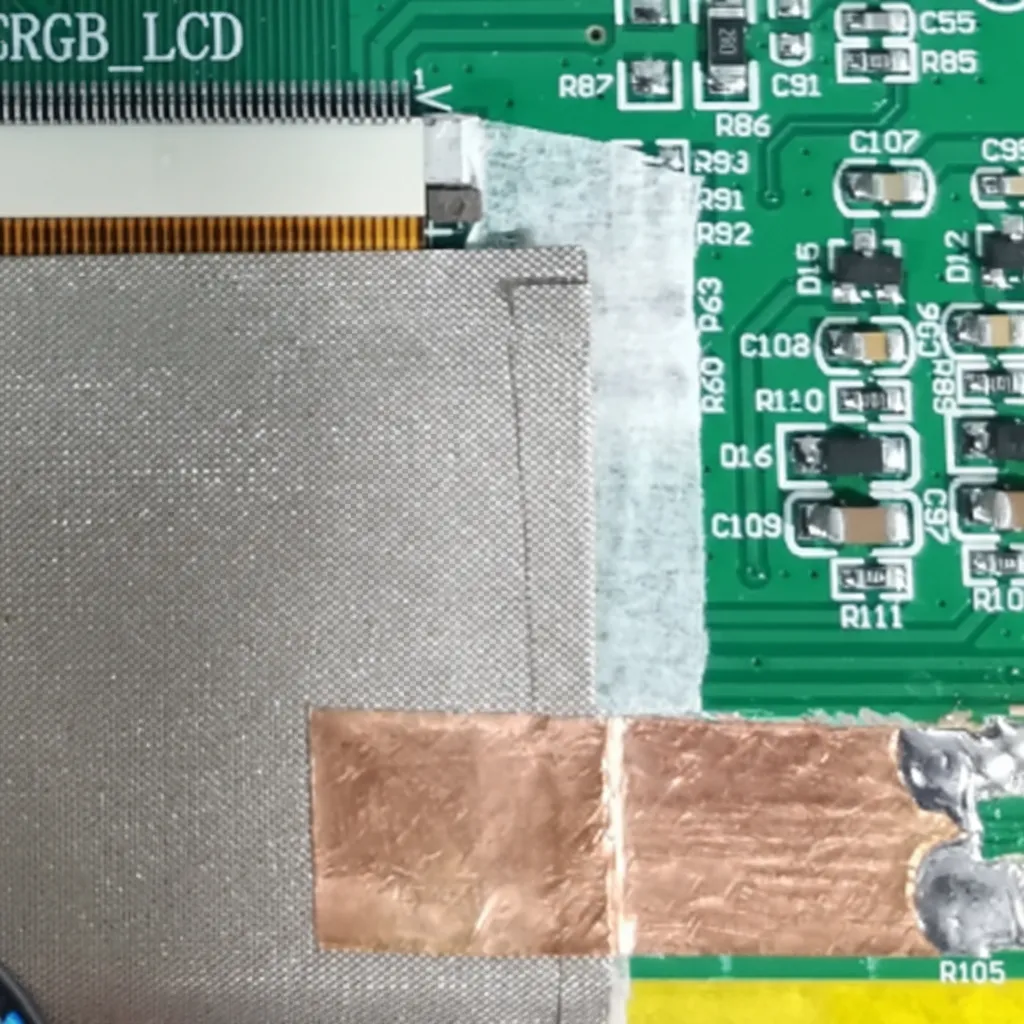
(2) Add capacitive filtering on the clock line of the cable from the chip to the display. Capacitance is chosen according to data rate; here a 47 pF capacitor to ground was added.
(3) Shield and ground the display ribbon cable.
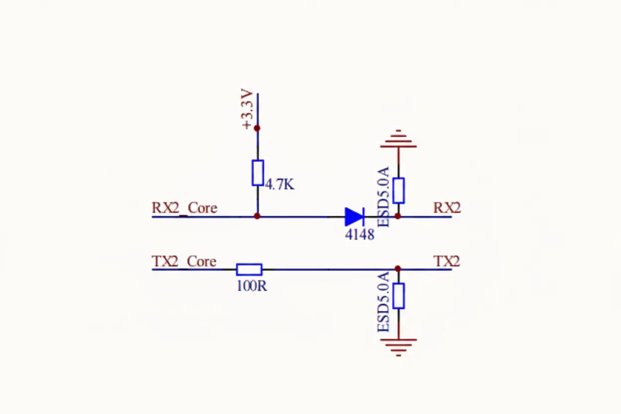
After these three measures we tested in an anechoic chamber. The clock emissions were reduced but still slightly above the limit. We suspected the clock was coupling onto other signal lines and radiating. Using a spectrum analyzer to scan signal lines near the clock, we found a strong clock component on the TX line, so we added an RC filter directly on the TX line. In addition, the PCB ground and the display ground were not connected; an insulating layer separated them, so we tied the grounds together. Beyond the three standard measures, we added two more actions.
(4) Add an RC filter on the TX signal. Since the line already had a 100 ohm resistor, we added a 47 pF capacitor at that point.
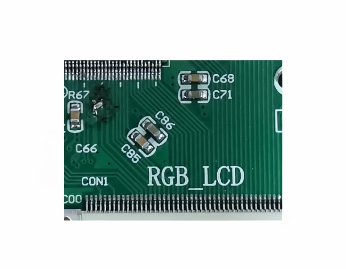
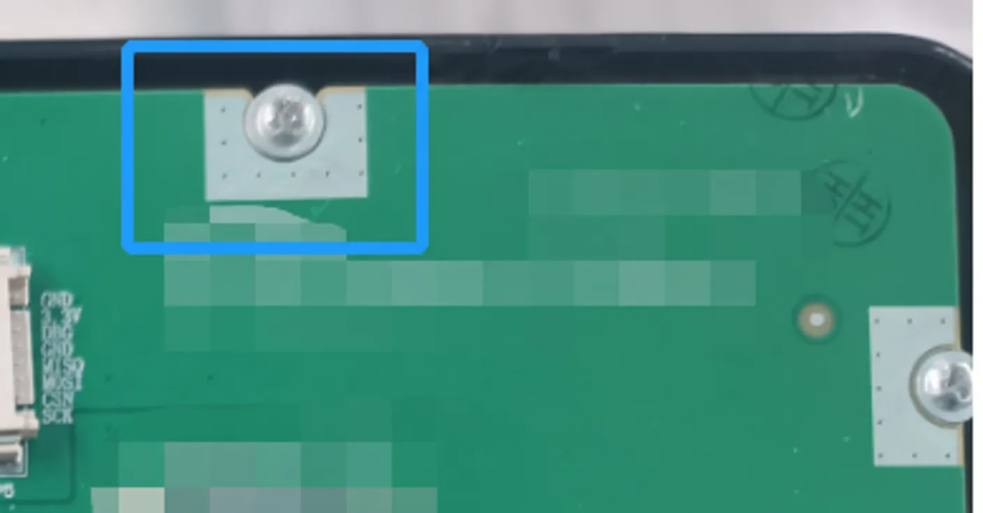
(5) Connect the PCB ground and the display ground through the mounting screw hole.
Final chamber test results were as follows:
The test results provided adequate margin. A spread-spectrum IC was used, connected to the main clock as shown below.
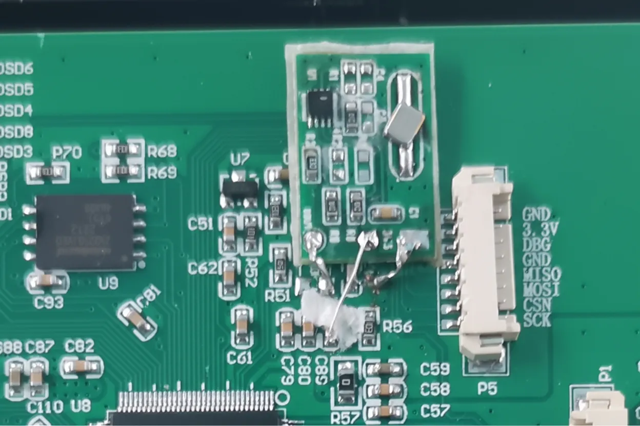
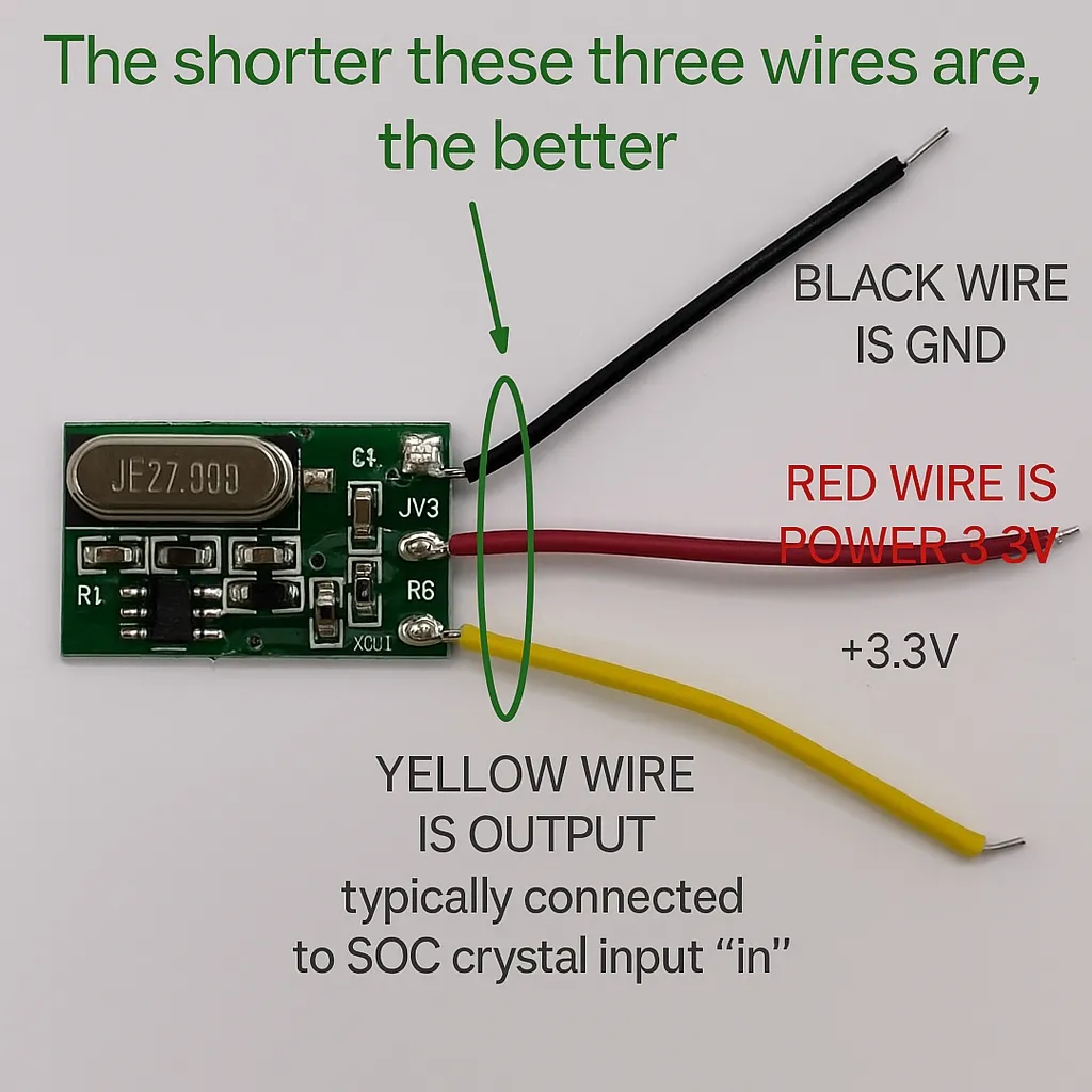
The spread-spectrum IC is connected to the main clock by removing the main crystal oscillator and soldering it to the spread-spectrum demo board. Provide a 3.3V power supply near the crystal. The demo board output connects to the original crystal input, and keep the demo board wiring as short as possible.
3. Summary
This case shows that clock-related emissions can be addressed by locating the source and applying proper filtering. Early design measures, including careful layout and use of spread-spectrum devices, can prevent later board revisions.


