ALLPCB


Electromagnetic radiation requires two conditions: an antenna and an alternating current flowing through the antenna.
Common antenna models include the current loop and the dipole.
1. Antenna models
1.1 Current-loop antenna
The field region of radiation can be divided into near field and far field according to the distance from the source.
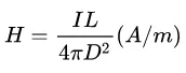
In the near field (distance D < wavelength/2pi) the magnetic and electric field magnitudes are as follows.
Magnetic field:
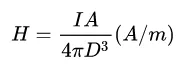
From the expression above, the near-field magnetic field magnitude is independent of frequency; DC and AC behave similarly. The magnetic field magnitude decays with the cube of distance, so increasing distance effectively reduces magnetic field strength.
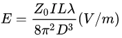
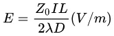
Electric field:
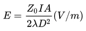
Z0 denotes the characteristic impedance of free space, which is about 377 ohm in air.
The near-field electric field magnitude increases as wavelength decreases (frequency increases) and decreases with the square of distance.
Both electric and magnetic field magnitudes are proportional to the loop area A.
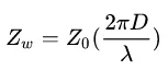
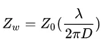
The near-field wave impedance of a current-loop antenna is:
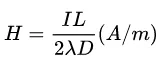
In the far field (D > wavelength/2pi) the magnetic and electric field magnitudes are:
Magnetic field:

Electric field:
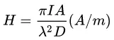
From these expressions, far-field magnetic and electric field magnitudes increase with the square of frequency. A square-wave pulse contains many high-frequency components and therefore can cause particularly strong interference.
1.2 Dipole antenna
A dipole antenna radiates only with alternating current because it is not a closed loop. It resembles a capacitor model and requires alternating voltage to form a current loop.
In the near field (distance D < wavelength/2pi) the magnetic and electric field magnitudes are:
Magnetic field:
Electric field:
The near-field wave impedance of the dipole antenna is:
In the far field (D > wavelength/2pi) the field strengths are:
Magnetic field:
Electric field:
In the above formulas, L is the dipole length.
In real circuits, any current loop or alternating voltage between two conductors produces parasitic antennas as described above. These antenna-model principles reveal how various factors affect radiation strength and provide theoretical guidance for electromagnetic shielding measures.
2. Shielding effectiveness
Loss when an electromagnetic wave passes through a shielding material consists of two parts: reflection loss and absorption loss. Shielding effectiveness (SE) is the sum of these two, with a correction for leakage.
SE = R + A + B
SE is shielding effectiveness, R is reflection loss, A is absorption loss, and B is the correction factor. When the shield thickness reaches about one skin depth, multiple-reflection leakage correction can be neglected; for electric-field waves, the correction factor can also often be ignored.
2.1 Reflection loss
An electromagnetic wave crossing a shield encounters two interfaces and undergoes two reflections.
Reflection loss is given by:
![]()
Zw is the wave impedance of the incident electromagnetic wave;
Zs is the characteristic impedance of the shielding material.
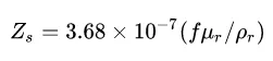
f is the frequency of the incident electromagnetic wave;
From the formulas above, once the shielding material is fixed, reflection loss depends on the wave impedance of the incident wave. Higher wave impedance yields greater reflection loss. Wave impedance differs between near field and far field.
In the near field, the wave impedance depends on the radiation source type. Magnetic-field sources have low impedance and thus low wave impedance and low reflection loss; electric-field sources have higher impedance and therefore larger reflection loss.
In the far field, wave impedance is independent of the source and depends only on the propagation medium; for example, wave impedance in air is 377 ohm, so the reflection loss becomes
![]()
From the shielding material impedance formula, materials with lower magnetic permeability and higher electrical conductivity have lower characteristic impedance and therefore larger reflection loss.
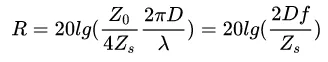
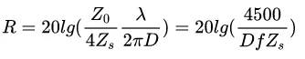
Substituting the near-field impedances of the current-loop and dipole antennas into the reflection loss formula yields:
Current-loop (primarily magnetic radiation) reflection loss:
Dipole (primarily electric radiation) reflection loss:
From these formulas, several conclusions follow:
(1) In near-field shielding, the electromagnetic wave type matters: electric-field waves have higher wave impedance and greater reflection loss; magnetic-field waves have lower wave impedance and smaller reflection loss.
(2) As frequency increases, reflection loss becomes independent of the radiation source type.
(3) The distance between the shield and the source affects reflection loss depending on the source type. For electric-field sources, closer distance increases reflection loss; for magnetic-field sources, the opposite is true.
2.2 Absorption loss
Absorption loss in the shielding material is:
![]()
L is the shield thickness.
Substituting the skin depth expression yields:
From the relation above:
(1) Absorption loss is independent of the electromagnetic wave type;
(2) Absorption loss depends on frequency: lower frequency yields smaller absorption loss, so low-frequency electromagnetic waves penetrate more readily;
(3) Greater shield thickness increases absorption loss;
(4) Materials with higher magnetic permeability and higher electrical conductivity provide greater absorption loss.
Based on the shielding-effectiveness curves in Figure 3, useful engineering conclusions include:
(1) At low frequency, shielding effectiveness depends on wave type. Absorption loss is small at low frequency, so shielding effectiveness is dominated by reflection loss, which depends on wave impedance. Thus at low frequency, electric-field waves are easier to shield than magnetic-field waves.
(2) At high frequency, shielding effectiveness is largely independent of wave type. As frequency increases, absorption loss grows and dominates shielding effectiveness; absorption loss is independent of wave type.
(3) Shielding effectiveness depends on wave type: electric-field waves are the easiest to shield, magnetic-field waves the hardest—especially low-frequency magnetic fields, since low frequency yields small absorption loss and the wave impedance is low, producing small reflection loss and therefore low overall shielding effectiveness.
From the conclusions above, recommended shielding measures can be summarized as follows:
(Near field) Electric-field shielding: electrostatic shielding and low-frequency alternating electric-field shielding — use well-grounded metallic conductors.
(Near field) Magnetic shielding: static magnetic shielding and low-frequency alternating magnetic-field shielding — use high-permeability materials (iron-nickel alloys) to form low-reluctance magnetic paths.
(Near field) High-frequency alternating magnetic-field shielding — use low-resistance conductors to generate eddy currents that produce opposing magnetic flux to suppress incident fields. Because permeability decreases and magnetic loss increases with frequency, high-frequency magnetic shielding typically uses low-resistance good conductors. Ferromagnetic materials are not suitable for high-frequency magnetic shielding.
(Far field) Electromagnetic shielding: shield high-frequency electromagnetic fields (high-frequency alternating electric fields produce time-varying magnetic fields and form electromagnetic fields) by using low-resistance conductive shielding materials to reflect and absorb waves, thereby isolating electromagnetic coupling.