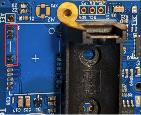
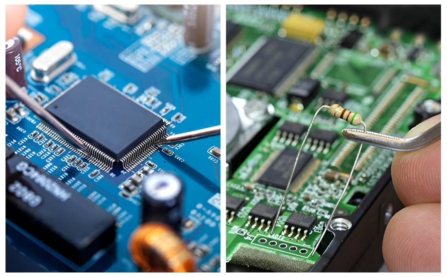
In the fast-paced world of electronics, high-density PCBs (Printed Circuit Boards) are at the heart of modern devices, packing more components into smaller spaces. However, this complexity brings challenges like solder bridges—unwanted connections between pads or traces that can cause shorts and failures. How can you prevent solder bridges in high-density PCB designs? The key lies in following precise design rules, optimizing pad spacing, and leveraging Design for Manufacturability (DFM) principles. In this blog, we’ll dive deep into actionable strategies for eliminating solder bridges, focusing on high-density PCB design rules, solder mask definition, pad spacing guidelines, DFM for solder bridge prevention, and minimizing shorts in SMT assembly.
Understanding Solder Bridges in High-Density PCBs
Solder bridges occur when excess solder forms an unintended connection between two or more conductive elements, such as pads or traces, during the assembly process. In high-density PCBs, where components are closely packed, the risk of solder bridges increases due to tighter spacing and smaller features. These defects can lead to electrical shorts, malfunctioning circuits, and costly rework.
The causes of solder bridges often stem from design oversights, manufacturing limitations, or assembly issues. For instance, pads placed too close together can allow solder to flow between them during reflow. Similarly, insufficient solder mask coverage might expose areas prone to bridging. By addressing these issues during the design phase, you can significantly reduce risks and improve the reliability of your boards.
High-Density PCB Design Rules for Solder Bridge Prevention
Designing high-density PCBs requires strict adherence to specific rules to ensure manufacturability and reliability. Here are some critical high-density PCB design rules to prevent solder bridges:
- Trace Width and Spacing: Maintain a minimum trace width and spacing based on your manufacturer’s capabilities. For instance, a common guideline is to use a trace width of at least 6 mils (0.006 inches) and a spacing of 6 mils between traces to avoid solder migration. These values may vary depending on the board’s complexity and the assembly process.
- Component Placement: Avoid placing components too close to each other. Ensure that there is enough room for solder paste application and reflow without overflow. A spacing of at least 0.3 mm between components in high-density areas is often recommended for SMT (Surface Mount Technology) assembly.
- Via Placement: Keep vias away from solder pads to prevent solder wicking into the via during reflow. A minimum distance of 10 mils (0.01 inches) between vias and pads can help, and adding teardrops to via connections can reduce stress and improve reliability.
Following these high-density PCB design rules sets a strong foundation for preventing solder bridges and ensuring a smoother manufacturing process.
Solder Mask Definition: A Critical Barrier Against Shorts
Solder mask definition refers to the process of designing and applying the solder mask layer—a protective coating that covers the PCB’s copper traces and prevents solder from adhering to unwanted areas. Proper solder mask definition is essential for minimizing shorts in SMT assembly and preventing solder bridges in high-density designs.
Here are key considerations for effective solder mask design:
- Solder Mask Clearance: Ensure adequate clearance around pads. A typical clearance of 3 mils (0.003 inches) on each side of a pad prevents the mask from overlapping and interfering with solder application. However, too much clearance can expose copper and increase the risk of bridging.
- Solder Mask Slivers: Avoid narrow slivers of solder mask between pads, as they can peel off during manufacturing or fail to provide adequate insulation. A minimum width of 4 mils (0.004 inches) for solder mask slivers is a common guideline.
- Mask Between Fine-Pitch Pads: For fine-pitch components (e.g., QFN or BGA packages with pad spacing below 0.5 mm), consider using a solder mask defined (SMD) pad design. This ensures the mask covers the area between pads, reducing the chance of solder bridging during reflow.
A well-designed solder mask acts as a barrier, guiding solder to stay on designated pads and preventing unintended connections. Always review your manufacturer’s capabilities to align your solder mask definition with their process tolerances.
Pad Spacing Guidelines: Precision in Layout
Pad spacing is a critical factor in preventing solder bridges, especially in high-density designs where space is limited. Insufficient spacing between pads can cause solder to flow from one pad to another during reflow, creating bridges. Following pad spacing guidelines ensures that your design accommodates manufacturing tolerances and assembly processes.
- Minimum Pad-to-Pad Spacing: For SMT components, maintain a minimum spacing of 0.2 mm (8 mils) between adjacent pads. For fine-pitch components like BGAs, increase this to 0.3 mm if possible, as tighter spacing increases the risk of bridging.
- Pad Shape and Orientation: Use oval or rectangular pads for components that are prone to bridging during wave soldering. Orient pads to align with the direction of travel through soldering equipment to minimize solder accumulation. For example, a pad-to-pad gap of 0.6 mm to 1.0 mm is ideal for wave soldering applications.
- Solder Thieves: In wave soldering, add solder thieves (extra pads) at the trailing edge of a component to capture excess solder and prevent it from forming bridges between active pads.
By adhering to these pad spacing guidelines, you can reduce the likelihood of solder bridges and improve the overall yield of your PCB assembly process.
DFM for Solder Bridge Prevention: Designing with Manufacturing in Mind
Design for Manufacturability (DFM) is the practice of designing PCBs in a way that optimizes the manufacturing and assembly process. When it comes to solder bridge prevention, DFM principles are invaluable for identifying potential issues before production begins. Implementing DFM for solder bridge prevention can save time, reduce costs, and improve the quality of your boards.
Here are some DFM strategies to eliminate solder bridges:
- Run DFM Checks Early: Use design software with built-in DFM analysis tools to check for spacing errors, solder mask issues, and trace width violations. Many tools can detect over 90% of potential spacing problems before you send your design for fabrication.
- Optimize Stencil Design: During SMT assembly, the stencil controls the amount of solder paste applied to pads. Ensure stencil apertures are slightly smaller than the pad size (e.g., 10% reduction) to prevent excess paste that could lead to bridges. For fine-pitch components, a stencil thickness of 0.1 mm (4 mils) is often ideal.
- Share Files Early: Send your Gerber files or design data to your manufacturer for feedback before finalizing the design. They may suggest adjustments, such as increasing via sizes from 6 mils to 8 mils, to match their equipment capabilities and avoid redesigns.
By incorporating DFM for solder bridge prevention into your workflow, you can achieve higher first-pass yields and minimize rework. Studies show that proper DFM practices can improve yield rates from 85% to 98%, cutting costs and lead times significantly.
Minimizing Shorts in SMT Assembly: Best Practices
Shorts in SMT assembly often result from solder bridges, misaligned components, or excess solder paste. Minimizing shorts in SMT assembly requires a combination of careful design, precise manufacturing, and thorough inspection. Here are actionable best practices to follow:
- Component Alignment: Ensure accurate placement of components during assembly. Misalignment can cause solder to connect adjacent pins, especially in fine-pitch packages. Automated optical inspection (AOI) systems can detect placement errors with over 95% accuracy.
- Reflow Profile Optimization: A well-tuned reflow profile prevents solder from flowing excessively. For example, maintain a peak temperature of 245°C for lead-free solder and a time above liquidus of 60-90 seconds to ensure proper wetting without overflow.
- Inspection and Testing: After assembly, use X-ray inspection for hidden joints (e.g., under BGA packages) to detect solder bridges. Electrical testing can also identify shorts before the board is deployed.
By focusing on these practices, you can achieve cleaner SMT assembly results and minimize shorts, ensuring your high-density PCBs perform as intended.
Additional Tips for High-Density PCB Success
Beyond the core strategies discussed, here are a few additional tips to enhance your high-density PCB designs and further reduce the risk of solder bridges:
- Use Fiducial Marks: Add fiducial marks to your PCB layout to improve alignment during assembly. Proper alignment reduces the chance of misapplied solder paste.
- Prototype and Test: Before full-scale production, create a quick-turn prototype to test your design under real-world conditions. Check for thermal performance (e.g., maximum temperature of 80°C for a 5W load) and signal integrity issues that could indirectly contribute to solder bridge risks.
- Collaborate with Your Manufacturer: Maintain open communication with your manufacturing partner. Their insights into process limitations can guide adjustments, such as increasing annular ring sizes or modifying surface treatments.
Conclusion: Building Reliability into High-Density PCBs
Eliminating solder bridges in high-density PCBs is a critical step toward achieving reliable, high-performance electronics. By following high-density PCB design rules, optimizing solder mask definition, adhering to pad spacing guidelines, applying DFM for solder bridge prevention, and focusing on minimizing shorts in SMT assembly, you can significantly reduce defects and improve production outcomes. These strategies not only prevent costly rework but also ensure your designs meet the demands of modern applications.
Start implementing these practices in your next project to create PCBs that excel in both design and manufacturability. With careful planning and attention to detail, you can build boards that stand up to the challenges of high-density layouts and deliver exceptional results.
 ALLPCB


