ALLPCB


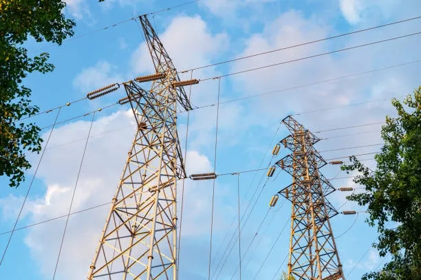
Real-time allocation of power from diverse sources to meet microgrid demand is a key research topic in smart grid projects. A common experimental approach is to build a laboratory simulation platform that replicates wind, solar, energy storage, electric vehicle charging stations, power motors, conventional loads such as household appliances, and even real facilities. All of these are connected through a controlled grid simulator to study how different supply sources and loads behave under various conditions.
Role and requirements of the grid simulator
The grid simulator acts as the core connection among devices on the test platform. By adjusting its output it can emulate a wide range of normal and fault conditions on a real network, allowing observation and evaluation of attached devices for subsequent improvement. This requires strong voltage and frequency regulation, good support for bidirectional power flow, and the ability to accept external control commands in real time. As experiments push toward hardware-in-the-loop simulation, the real-time control demands and waveform complexity increase, putting stricter requirements on the simulator compared with an ordinary AC source.
Typical control methods include front-panel operation or remote control via SCPI commands over GPIB, RS232, USB, or Ethernet. These methods generally cannot meet the latency and waveform complexity requirements for hard real-time outputs. A lower-latency approach is to use external analog signals to directly control the simulator output. In that mode the simulator effectively behaves like a linear amplifier, scaling the external analog signal and providing the corresponding output power.
Real-time digital simulation (RTDS)
Commercial tools are available to generate the complex external control signals needed for realistic scenarios. Real Time Digital Simulation (RTDS) systems are powerful hardware and software platforms. They provide a comprehensive power system component module library and a graphical interface that lets users assemble circuits and set test sequences. RTDS can continuously produce outputs that represent real network conditions, simulate many realistic adverse scenarios, and offer numerous digital and analog I/O interfaces that can connect directly to external equipment.
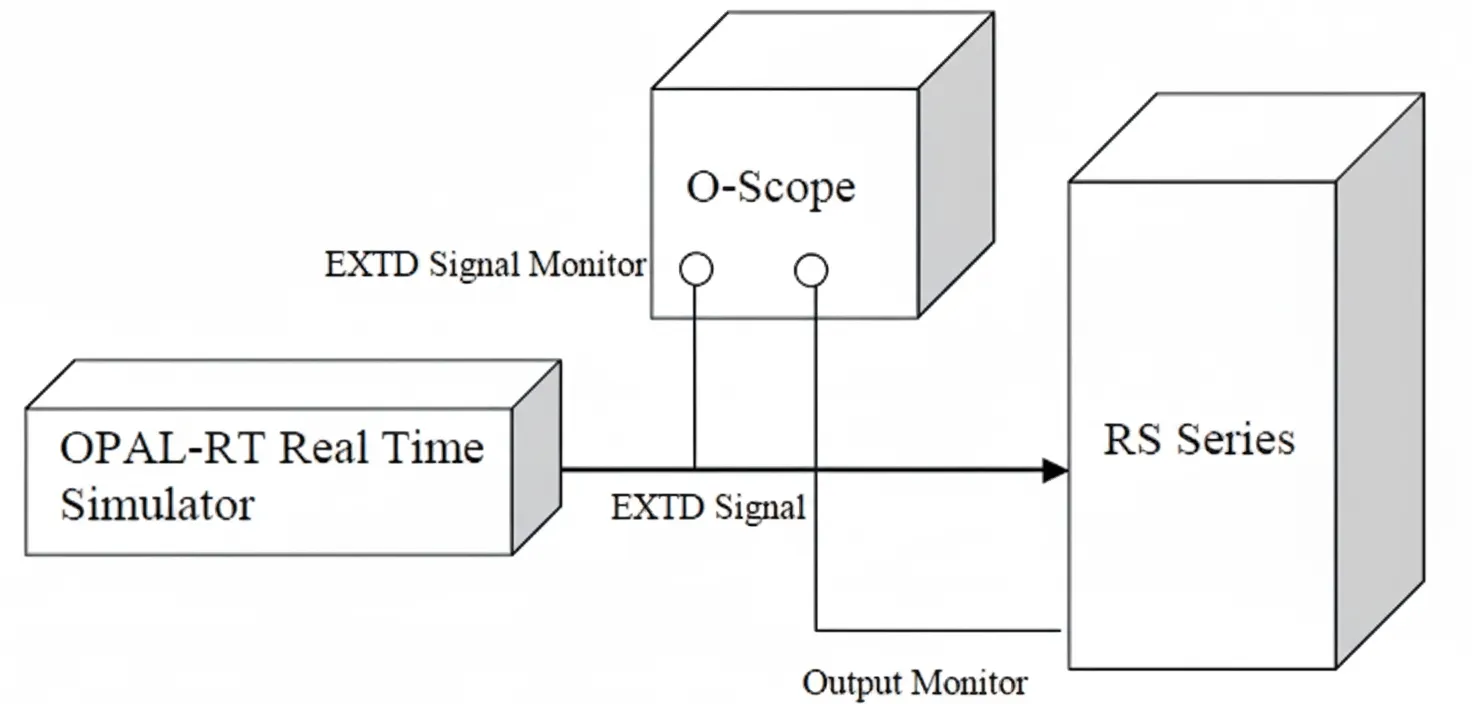
Test platform components
In our setup we used AMETEK California Instruments (CI) RS series high-power AC sources as the grid simulator paired with an RTDS system. The RS series provides 90 kVA to 1 MVA output, supports 100% bidirectional power flow, and has a stable output frequency range of 16 Hz to 820 Hz. It also supports DC output. The external analog control interface accepts 0 to 7 V AC input corresponding to 0 to full-scale output voltage, and each of the three phases can be independently controlled by its own analog input.
The RS source was tested together with a Canadian real-time controller to validate system performance.
System configuration
System test configuration is shown below.
Note that the CI RS source is a switched-mode power supply with inherent control limits. Its internal controller will normally reject out-of-range frequency or voltage requests. When controlled by an external analog signal for improved real-time performance, the external signal drives the RS power modules directly and bypasses the internal controller. Therefore the hardware design must consider the risk of overlimit inputs or high interference on the analog input to avoid damage to the power modules.
The RS units include a filter on the external analog input to remove high-frequency noise. Protection measures are also in place to handle cases where the control signal exceeds the unit's capabilities.
Verification procedure and results
The following tests and observations summarize the verification process.
-
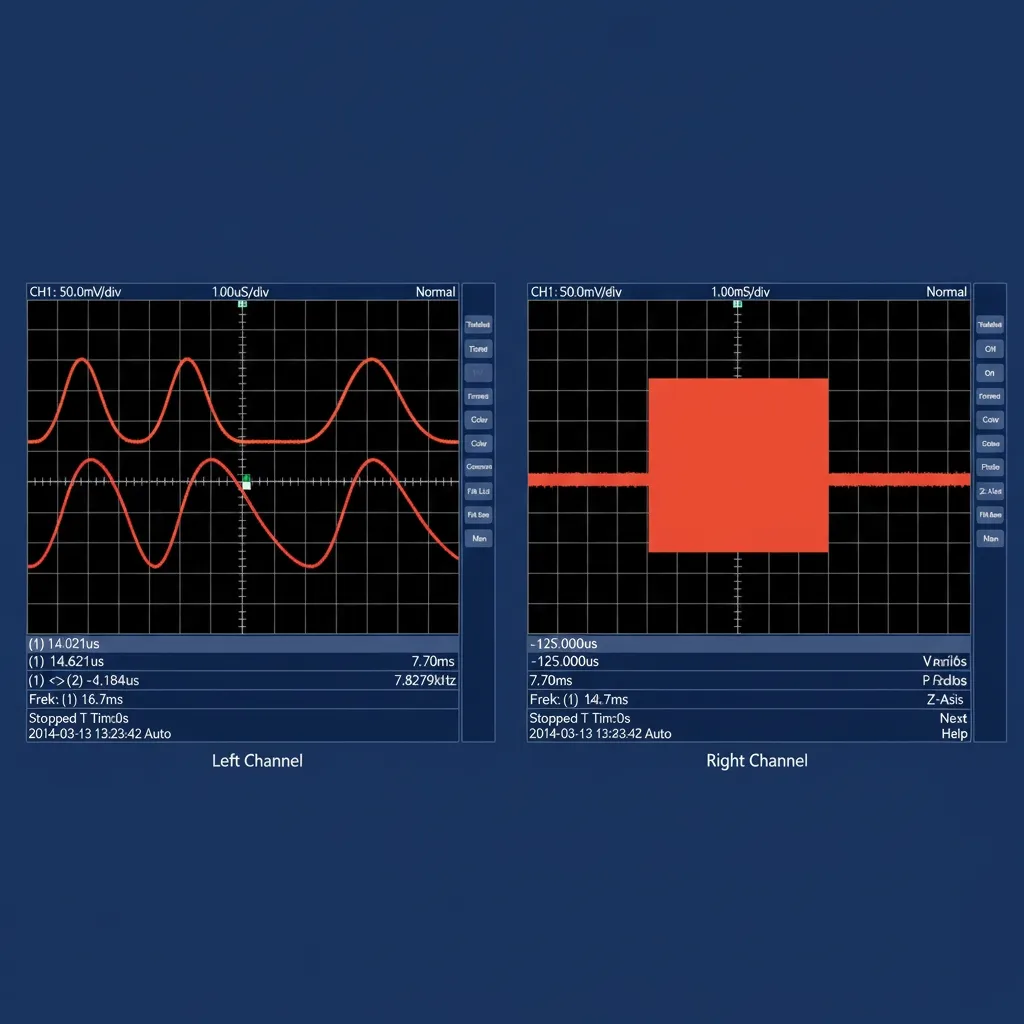
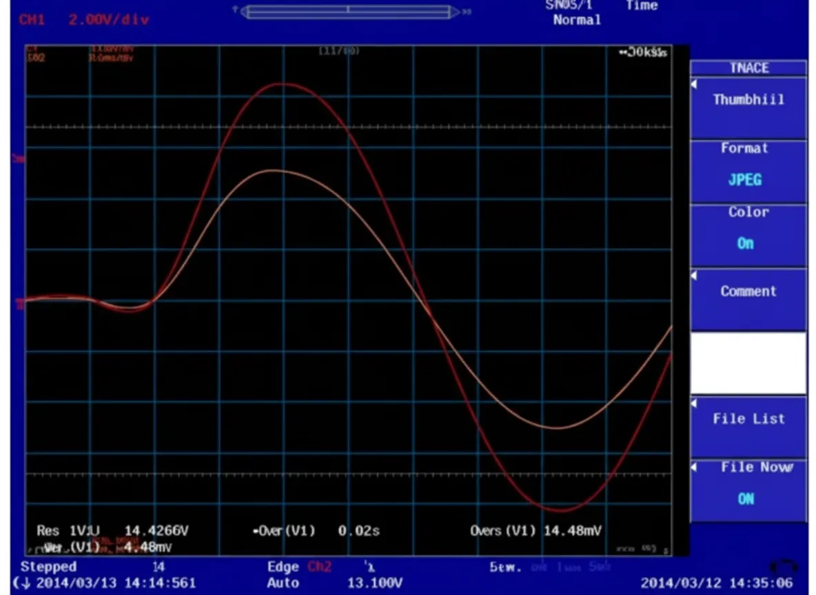
60 Hz sine and square wave tracking. Initial waveform checks showed the CI RS source follows the real-time controller signal well. The oscilloscope traces show the controller signal in orange and the RS output voltage in red. Measured latency when accepting external analog control is approximately 100 microseconds.
-
60 Hz sine ramp-up from 0 V to 230 V.
-
60 Hz sine ramp-down from 230 V and hard shutdown.
-
60 Hz sine shutdown with 1 ms ramp at 90 degree point.
-
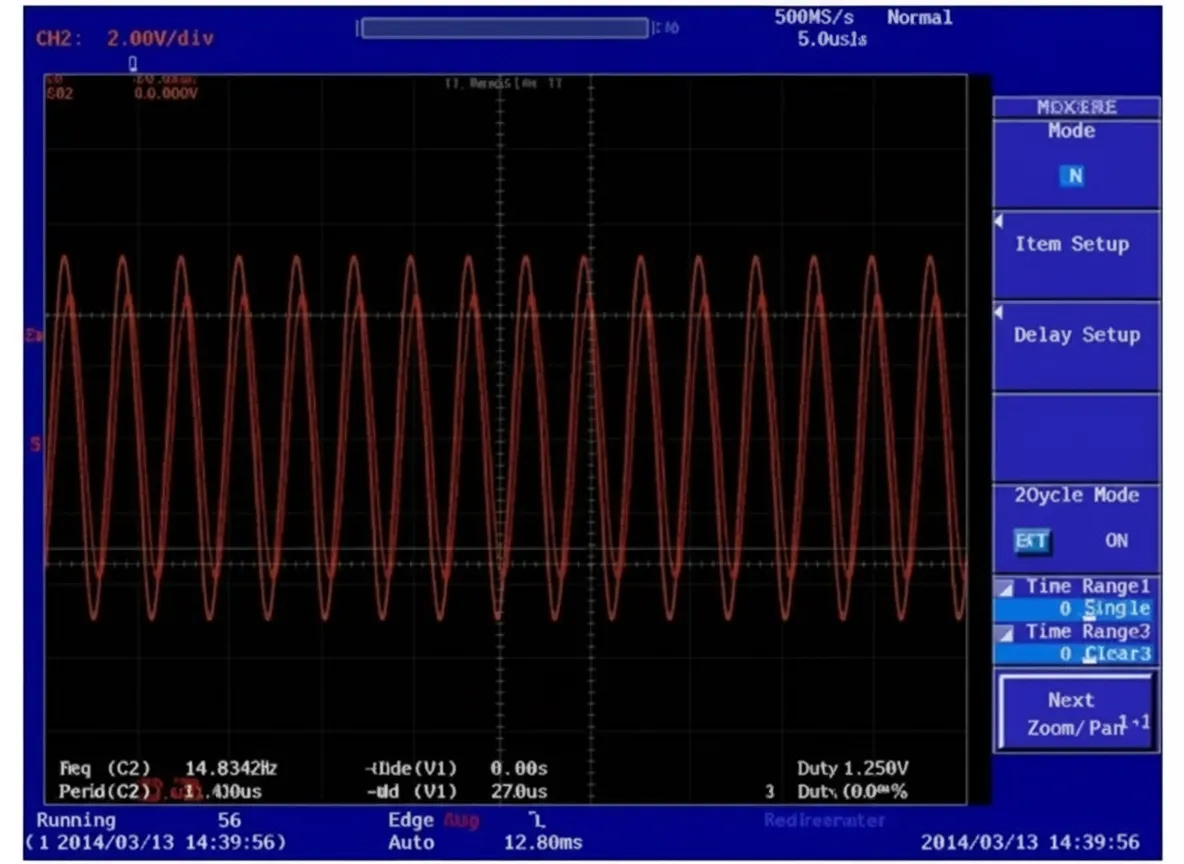
800 Hz output. The RS external analog control frequency limit is 819 Hz; when reverse power is enabled the limit is 500 Hz. Exceeding these limits triggers automatic output cutoff for protection. The following shows 230 V at 800 Hz under external analog control.
-
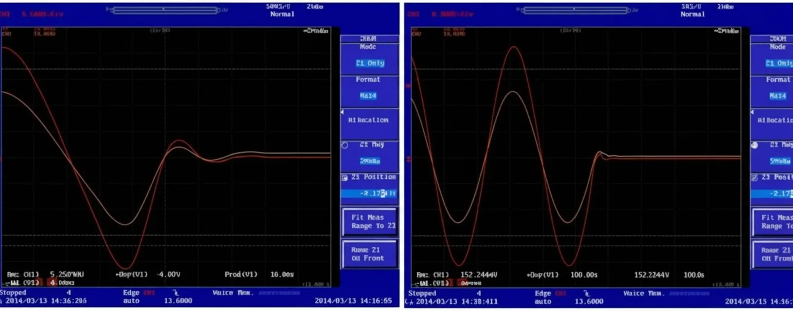
60 Hz 230 V triangle wave. Right-hand image shows a zoomed detail.
-
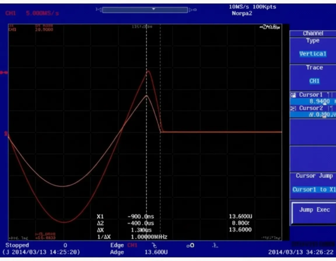
High-frequency protection. When the external analog command requests an output frequency above the allowable limit, the RS unit disables output automatically after about 150 ms. The right image shows a zoom of the shutdown moment.
-
230 V 60 Hz sine with 400 Hz ripple noise, 85 Vpp. Right image shows a zoomed detail.
-
215 V low slew-rate square wave, rise time approx. 2 ms. Right image shows a zoomed detail. Performance was good.
-
215 V high slew-rate square wave, rise time approx. 30 microseconds. Right image shows a zoomed detail. When the requested voltage slew rate exceeds the RS capability, the output exhibits ringing.
-
Load tests. The RS operates as a voltage source, so current is determined by the load. Current output behavior is independent of whether the RS is controlled from its internal controller or via external analog input. Existing applications have shown good current performance across various waveforms when using the RS internal controller. The waveform below, from a South Korean research institute, shows a ground fault simulation controlled by RTDS with a load of 30 kW + 10 kVA. Yellow is phase A voltage, purple is phase B voltage, green is phase A current, and blue is the RTDS control signal for phase A voltage.
Conclusions
Based on the verification tests, the AMETEK CI RS series power hardware demonstrates robust design and acceptable latency of about 100 microseconds when driven by external analog control. Combined with an RTDS system, the platform can provide a realistic microgrid simulation environment covering 90 kVA to 1 MVA. This configuration supports simulation of complex power scenarios and integration of renewable generation, loads, and energy storage for laboratory research and validation.