ALLPCB


Test Scenarios
DDR4 signal testing falls into several scenarios:
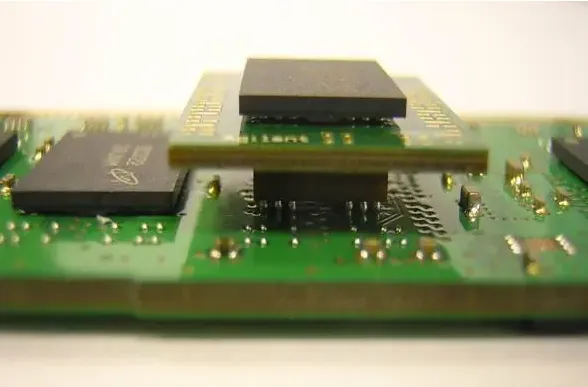
- Mobile devices with multiple stacked or closely placed package-on-board memory components. Because the controller and memory packages are adjacent and signals are not routed through vias, test points are not available on the board; testing requires an interposer.
- Single-sided surface-mount packages (typical for TV applications). These can be tested with an interposer when available; otherwise the vias and solder resist can be scraped to access traces for probing. In some cases differential DQS traces on the top layer with 4 mil spacing are soldered as shown below.
- UDIMM modules for PCs. These are the simplest case: single-sided memory modules expose signal vias on the back side that can be used as test points.
- Server RDIMM and laptop SODIMM modules are typically double-sided and often require an interposer for full testing.
An alternative technique is to remove one memory package from the back side of an RDIMM and modify the SPD information to treat the module as single-sided. Although capacity is halved, signal testing is not affected and test points become available. For long motherboard routes this single-package removal has a negligible impact on branching; this method has been validated in practice.
Read/Write Waveform Separation
To separate read and write waveforms use single-shot triggering to capture a single read or write event. Read waveforms show DQS and DQ in phase. Write waveforms show DQS and DQ approximately 90 degrees out of phase.
After triggering a single event, stacked waveforms can be separated by:
- Using the captured waveform and applying a visual/graphical trigger to select the general logic region (in or out). Keysight oscilloscopes support InfiniiScan for this purpose.
- Examining single-shot read and write DQS patterns: the first two high/low pulse widths differ between read and write. Use the oscilloscope width(trigger) function to trigger on DQS.
Note 1: Tektronix Visual Trigger and Keysight InfiniiScan are licensed options that must be purchased separately; they are very effective for separating read and write events.
Note 2: The DDR3 method of using the direction of the preamble to separate read and write is ineffective for DDR4, since DDR4 preamble direction is not fixed and may be identical for read and write.
DDR4 Pin Descriptions
The following table summarizes common DDR4 pin functions.
| Symbol | Type | Function |
|---|---|---|
| CK_t, CK_c | Input | Clock: CK_t and CK_c are differential clock inputs. Address and control inputs are sampled on the crossing of the positive edge of CK_t and negative edge of CK_c. |
| CKE, (CKE1) | Input | Clock enable: CKE HIGH activates internal clocks and input/output drivers; CKE LOW deactivates them and enables power-down/self-refresh modes. CKE must be held high during read and write accesses. Input buffers (excluding CK_t/CK_c, ODT and CKE) are disabled during power-down; input buffers (excluding CKE) are disabled during self-refresh. |
| CS_n, (CS1_n) | Input | Chip select: When CS_n is HIGH, commands are masked. CS_n supports external rank selection on multi-rank systems and is part of the command code. |
| C0, C1, C2 | Input | Chip ID: Used for 3DS stacked devices via TSV to select slices of the stacked component; considered part of the command code. |
| ODT, (ODT1) | Input | On-die termination: When ODT is registered HIGH, the device enables internal RTT_NOM termination for DQ, DQS_t/DQS_c and related mask/TDQS signals depending on device width and mode register settings. If MR1 disables RTT_NOM, ODT is ignored. |
| ACT_n | Input | Activation command input: With ACT_n low, RAS_n/A16, CAS_n/A15 and WE_n/A14 are interpreted as row address bits A16-A14. |
| RAS_n/A16, CAS_n/A15, WE_n/A14 | Input | Command inputs: These pins are multi-function. With ACT_n low they serve as address bits; with ACT_n high they act as command pins as defined in the command truth table. |
| DM_n/DBI_n/TDQS_t, (DMU_n/DBIU_n), (DML_n/DBIL_n) | Input/Output | Data mask and data bus inversion: DM_n masks write data when sampled LOW (sampled on both edges of DQS). DM is multiplexed with DBI by mode register settings. DBI specifies whether data is stored/output inverted. TDQS is supported only for x8 devices when enabled via MR1. |
| BG0 - BG1 | Input | Bank group inputs: Define the target bank group for commands. BG0 also selects the mode register during a MRS cycle. x4/x8 devices have BG0 and BG1; x16 has only BG0. |
| BA0 - BA1 | Input | Bank address inputs: Define the target bank for commands and which mode register to access during a MRS cycle. |
| A0 - A17 | Input | Address inputs: Provide row addresses for ACTIVATE and column addresses for Read/Write. Some pins have additional functions (A10/AP, A12/BC_n, RAS_n/A16, CAS_n/A15, WE_n/A14). A17 is defined only for x4 configuration. |
| A10 / AP | Input | Auto-precharge: A10 is sampled during Read/Write to determine whether auto-precharge is performed after the operation (HIGH = auto-precharge). During Precharge, A10 selects precharge scope (A10 LOW = single bank; A10 HIGH = all banks). |
| A12 / BC_n | Input | Burst chop: Sampled during Read/Write to determine whether burst chopping occurs (HIGH = no chop; LOW = burst chopped). |
| RESET_n | Input | Active-low asynchronous reset. RESET_n must be HIGH during normal operation. RESET_n is a CMOS rail-to-rail signal with DC thresholds at 80% and 20% of VDD. |
| DQ | Input/Output | Bi-directional data bus. If CRC is enabled, CRC code is appended to the end of the burst. Some DQ pins may indicate internal Vref during test via mode register settings; refer to vendor datasheets. |
| DQS_t, DQS_c, DQSU_t, DQSU_c, DQSL_t, DQSL_c | Input/Output | Data strobe: Output with read data, input with write data. Edge-aligned with read data and centered in write data. DDR4 supports differential data strobe only, not single-ended. |
| TDQS_t, TDQS_c | Output | Termination data strobe: Applicable for x8 devices when enabled via MR1. When enabled, the same termination function as DQS is applied. x4/x16 devices must disable TDQS via MR1. |
| PAR | Input | Command and address parity input: Even parity checking is supported when enabled via mode register. Parity is calculated over command and address signals and must be valid at the rising edge of the clock with CS_n low. |
| ALERT_n | Input/Output | Multi-function alert signal: can indicate CRC or parity errors by driving low. During connectivity test mode this pin is an input. If not used, ALERT_n should be pulled to VDD on the board. |
| TEN | Input | Connectivity test mode enable: Required for x16 devices and optional for x4/x8 devices of higher density. When HIGH it enables connectivity test mode. This pin may be weakly pulled low internally. |
| NC | No connect | No internal electrical connection. |
| VDDQ | Supply | DQ power supply: 1.2 V +/- 0.06 V. |
| VSSQ | Supply | DQ ground. |
| VDD | Supply | Power supply: 1.2 V +/- 0.06 V. |
| VSS | Supply | Ground. |
| VPP | Supply | DRAM activation power supply: nominal 2.5 V (2.375 V min, 2.75 V max). |
| VREFCA | Supply | Reference voltage for command/address (CA). |
| ZQ | Supply | Reference pin for ZQ calibration. |
Test Preparation
Recommended tools and consumables: soldering station, reballing board or temperature-controlled rework station, DDR device(s), tweezers, soldering iron, DDR adapter board, flux, desolder braid, solder balls. Test instrument used in this article: Tektronix DSA71254 12.5 GHz, 100 GS/s. Probes: P7313 (13 GHz x4) or P7513.
Test Items Overview
DDR testing typically covers:
- Timing measurements
- Ripple (power supply) measurements
- Signal integrity measurements, which include clock, command/address, write and read measurements
Component vendors often sample a subset of channels and signals rather than performing exhaustive tests. If resources permit, a full test can be performed by repeating the procedures for all DQ lines, though in most cases sampling a representative set of signals is sufficient.
Timing Measurements
Timing measurements cover items such as power-up/reset sequencing and various timing constraints. Examples include:
- VDD to RESET: after power-up, VDD high then RESET high. Requirement: minimum 200 us.
- RESET to CKE: after reset high, enable CKE. Requirement: minimum 500 us.
- tCKSRX: Clock stabilization to CKE enable. Requirement: min = max(5 nCK, 10 ns).
Power-down mode requires additional timing tests such as tPD (power-down entry) and tCKE. Example constraints:
- tPD: min tCKE(min), max 9*tREFI
- tCKE: min = max(3 nCK, 5 ns)
- tXP: min = max(3 nCK, 6 ns)
- tREFI: refresh interval varies with temperature
tRFC (self-refresh enable time): requirement min 260 ns.
When testing these timings use logic triggering with the appropriate logic pattern. In normal operation (not power-down), RESET and CKE should both remain high.
Ripple Measurements
Measure ripple on the following rails:
- VDD: < 75 mV
- VrefCA: <= 60 mV
- VrefDQ: <= 60 mV
Measure according to standard ripple measurement techniques.
Signal Integrity Measurements
Clock Measurements
Jitter-related parameters include period jitter, cycle-to-cycle jitter, and duty-cycle distortion. For example, at DDR4-2666:
Jitter can be measured manually or automatically. Manual measurement requires displaying about 200 clock cycles and adding measurements such as positive width, negative width, period, and frequency.
Automatic measurement requires the oscilloscope's DDR analysis feature (typically a licensed option). Select the clock test, the channel used for the clock, and the DDR rate. Run continuously to check for errors and export a report if needed.
Command and Address Measurements
Command/address signals to test include CS#, RAS#, CAS#, WE#, address lines and bank address lines. For DDR4 the setup and hold tests do not reference slope; the conditions are:
- tIS > tIS(base)
- tIH > tIH(base)
The reference voltage levels for setup/hold are AC 100% and DC 75% thresholds. It is useful to include CS as a reference in the test waveform since CA signals are valid when CS is low.
Write Data Measurements
Both read and write data measurements use DQS as the timing reference for DQ, not CLK. For DDR4 write measurements the focus is on eye diagrams rather than classic setup/hold windows used in DDR3.
Eye-width and eye-height requirements are shown below.

Example write waveform:

Test schematic:
tDQSS is the phase difference between CLK and DQS; example waveform:
Read Data Measurements
Key read parameters include tDQSQ, tQH and tDQSCK. Example measurement diagram:
tDQSQ requirements vary with DDR rate (values shown in vendor tables). tQH requirement: min = 0.38 * tCK.
Oscilloscope capture examples (DPO71254) for tDQSQ and tQH:
When testing, accumulate multiple captures to observe the overall waveform trends.
tDQSCK measures the relationship between the read data clock and read DQS. Example capture:

Parameter limits depend on DDR rate; refer to vendor tables for specific min/max values.
When testing read and write data, select representative high-bit and low-bit DQ lines for measurement.
Typical Limits by Speed
| Metric | DDR3 1600 | DDR3 1866 | DDR3 2133 | DDR4 2400 |
|---|---|---|---|---|
| Frequency range (f) | [303, 800 MHz] | [303, 933 MHz] | [303, 1066 MHz] | [1066, 2400 MHz] |
| tCK(avg) | [1.25, 3.3 ns] | [1.07, 3.3 ns] | [0.938, 3.3 ns] | [0.833, 0.938 ns] |
| Duty cycle | [47, 53%] | [47, 53%] | [47, 53%] | [48, 52%] |
| CC Jitter (ps) | ±140 | ±120 | ±100 | ±83 |
| VIX | [600, 900 mV] | [600, 900 mV] | [600, 900 mV] | [480, 720 mV] |
| tDQSS | ±0.27 tCK | ±0.27 tCK | ±0.27 tCK | ±0.27 tCK |
| Mask | Crossing ±70 mV, min 84 ps |
Vendor Test Items
Different memory vendors have similar test item sets. Example comparisons for Samsung and SK Hynix are summarized; both vendors measure clock parameters, duty cycle, timing, DQ/DQS parameters and power ripple. Vendor-specific thresholds and which signals are measured may differ. Refer to vendor-specific test documents for full details.
| Category | Samsung test items | SK Hynix test items |
|---|---|---|
| Clock (differential) | tCK(avg), tCH(avg), tCL(avg), duty cycle | tCK(avg), tCH(avg), tCL(avg), duty cycle |
| Single-ended clock | VIX limits (min/max) | VIX limits (min/max) |
| Command & Address | tIS, tIH, slew rates, VIH/VIL, overshoot/undershoot | tIS, tIH, slew rates, VIH/VIL, overshoot/undershoot |
| DQ/DQS | Write/read timing and eye metrics, VIH/VIL relative to Vref, overshoot/undershoot | Write/read timing and eye metrics, VIH/VIL relative to Vref, overshoot/undershoot |
| Power | VDD/Vref ripple; some vendors measure ripple on a single device sample | VDD/Vref ripple; similar requirements |
| Timing | Reset rise to CKE rise: min 500 us, tCKSRX: min = max(5 nCK, 10 ns) | Reset rise to CKE rise: min 500 us, similar timing checks |
Summary
For DDR4 testing, manual testing is often preferable because manual read/write separation provides clear accumulated waveforms. Exhaustive testing of every signal is not always necessary; representative sampling across types is usually sufficient.