 ALLPCB


Standard panel dimensions have long served as the foundation for efficient printed circuit board production. Manufacturers optimize equipment, material handling, and throughput around these fixed formats. Engineers and procurement teams encounter situations where a design does not align with those dimensions. In such cases, custom PCB panel sizes become a practical consideration. The decision involves balancing design requirements against manufacturing realities. Non-standard PCB panel size choices affect material yield, assembly compatibility, and overall project timelines.
What Custom PCB Panel Sizes Mean in Practice
A custom PCB panel size deviates from the rectangular formats that most fabrication lines accept without modification. Standard panels allow automated loading, consistent fixturing, and predictable processing through etching, drilling, and plating stages. When a board outline or array layout exceeds those boundaries, or when multiple unique designs share a single production run, a non-standard PCB panel size may improve utilization. The approach requires coordination between design and production teams to confirm that equipment can accommodate the new dimensi
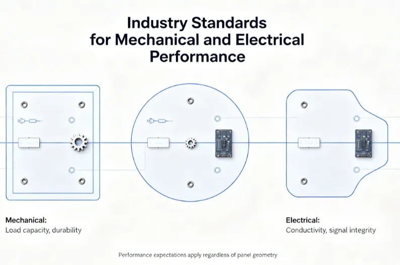
Engineering Factors That Influence Panel Size Decisions
Panel flatness, edge clearance, and fiducial placement remain critical regardless of overall dimensions. Warpage limits defined in IPC standards help ensure reliable component placement during assembly. Larger or irregularly shaped panels can introduce additional stress during thermal cycles, potentially affecting registration accuracy between layers. Designers evaluate copper distribution, dielectric thickness, and reinforcement patterns to maintain stability. 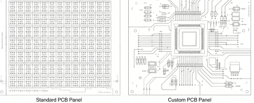
Material utilization calculations consider both the active board area and the surrounding frame required for handling and testing. Non-standard sizes may reduce scrap when boards feature complex outlines or when multiple small designs fit more efficiently on a single sheet. Conversely, very large panels can exceed the travel limits of certain drilling or routing machines, requiring segmented processing or specialized carriers. Thermal expansion characteristics of the laminate must also align with the chosen panel dimensions to avoid registration issues during multilayer lamination.
Advantages of Custom PCB Panels
Custom PCB panel sizes allow tighter nesting of boards that do not conform to rectangular grids. This arrangement can lower the amount of unused laminate per production lot. For prototypes or low-volume runs containing several dissimilar designs, a single custom panel reduces the number of separate setups. Assembly lines benefit when the panel matches the exact footprint needed for a particular fixture or carrier, minimizing manual intervention.
Another advantage appears in designs that incorporate large connectors or mechanical features near the board edge. A tailored panel size can position these features away from the handling margins, improving yield. When combined with careful array planning, the approach supports consistent solder paste deposition across all units.
Disadvantages and Limitations of Non-Standard Sizes
Non-standard PCB panel size selections often require additional engineering review and possible machine adjustments. Setup time increases because operators must verify alignment, vacuum hold-down, and conveyor compatibility. Some automated optical inspection systems expect fixed panel dimensions, so custom sizes may necessitate new programming or manual inspection steps. (Insert image: 'Assembly Line Handling' · ALT: 'Technician loading a custom-sized PCB panel into a pick-and-place machine')
Lead times can extend when the fabrication facility must source or cut laminate to the new dimensions. Inventory management becomes more complex because leftover material from one custom run rarely matches the requirements of future orders. In high-volume production, the cumulative effect on throughput frequently outweighs the material savings achieved on individual lots.
Cost Considerations for Custom PCB Panel Sizes
The cost of custom PCB panel size decisions appears in both direct and indirect categories. Direct costs include laminate cutting, additional fixturing, and potential requalification of processes. Indirect costs arise from longer cycle times and the need for extra quality checks to confirm dimensional stability. When material waste decreases significantly, the net effect can be neutral or even favorable for certain designs. Engineers typically request a panelization review early in the layout phase to quantify these trade-offs before committing to a non-standard format.
Best Practices for Evaluating Panel Size Options
Begin with a thorough review of the board outline and array requirements against the capabilities of the intended fabrication and assembly partners. Consider IPC guidelines for dimensional tolerances and surface finish acceptance when defining the panel frame. Maintain consistent fiducial placement and tooling hole locations even when overall dimensions change. Document the rationale for any deviation from standard sizes so that future revisions can reference the same constraints. 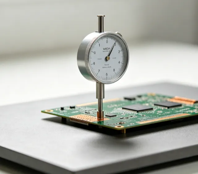
Pilot runs provide valuable data on actual yield and handling performance. Feedback from these runs informs whether the custom size delivers measurable benefits or whether minor design adjustments could restore compatibility with standard panels.
Conclusion
Custom PCB panel sizes offer targeted solutions when standard formats limit design flexibility or material efficiency. The choice requires careful evaluation of manufacturing constraints, quality requirements, and total cost. Reference to established standards helps maintain consistent performance expectations across both standard and non-standard approaches. Teams that integrate panel size considerations early in the design cycle achieve more predictable outcomes and smoother transitions from prototype to production.
FAQs
Q1: What are the main advantages of custom PCB panels?
A1: Custom PCB panels can improve material utilization when board shapes do not fit efficiently into standard rectangles. They also allow multiple dissimilar designs to share a single production lot, reducing setup frequency. Engineers gain flexibility in positioning critical features away from handling edges. These benefits appear most clearly in low-to-medium volume runs or complex outlines. The approach still requires verification against assembly equipment limits.
Q2: How does a non-standard PCB panel size affect manufacturing cost?
A2: A non-standard PCB panel size typically increases initial setup and fixturing expenses. Additional time for alignment checks and possible machine adjustments contributes to higher per-lot costs. Material savings from better nesting may offset some of these expenses, depending on the design. Procurement teams usually request detailed panelization quotes to compare total ownership costs. Early collaboration with the fabricator helps identify the break-even point.
Q3: When should engineers consider custom PCB panel sizes?
A3: Engineers should evaluate custom PCB panel sizes when standard dimensions force excessive waste or prevent proper array layout. Designs with large mechanical features or irregular outlines often benefit from tailored panels. Low-volume production containing several unique boards can also justify the change. The decision balances potential yield gains against longer lead times and equipment compatibility checks.
Q4: What standards guide the use of custom PCB panel sizes?
A4: IPC-6012E outlines qualification requirements for rigid printed boards, including dimensional and flatness criteria that apply regardless of panel size. IPC-A-600K provides visual acceptance criteria that remain relevant for both standard and custom formats. These documents help ensure consistent quality when panel dimensions deviate from common practice.
References
IPC-6012E — Qualification and Performance Specification for Rigid Printed Boards. IPC, 2017
IPC-A-600K — Acceptability of Printed Boards. IPC, 2020
ISO 9001:2015 — Quality Management Systems. ISO, 2015





