ALLPCB


Overview
Boost converters are commonly used to raise battery voltage in portable and wearable devices. However, their operating behavior can negatively affect the signal-to-noise ratio (SNR) in optical sensing applications. This design note explains why that occurs and describes a power management IC (PMIC) with a buck-boost converter specifically designed to maximize SNR in optical detection.
Introduction
In the pursuit of longer battery life for wearable devices, power-saving techniques are widely applied. Some energy-saving architectures that reduce steady-state consumption can unintentionally impair the functions the device is designed to perform. This design note reviews common approaches to managing battery voltage in optical sensing applications and the limitations of those approaches. It then considers the advantages of using a PMIC with a buck-boost converter designed to address these limitations, improving sensor performance while maintaining low overall power consumption.
Optical Sensing
Optical sensors are commonly used to measure health metrics such as heart rate and blood oxygenation (SpO2). These measurements are based on photoplethysmography (PPG). A PPG signal is obtained by illuminating the skin with an LED and detecting changes in reflected light intensity with a photodiode. The photodiode generates a current proportional to the received light (Figure 2).
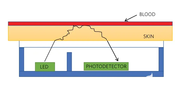
Figure 2. PPG signal using an LED and a photodiode.
The number and intensity of light pulses required for an accurate measurement depend on the use case and conditions. For example, measurements are more challenging during vigorous activity than during sleep. Ambient conditions and skin pigmentation also affect required LED drive current.
Battery Management
Some lithium battery chemistries have nominal voltages in a range from about 3.2 V to 4.35 V. A boost or buck-boost DC-DC converter is therefore used to raise battery voltage to the nominal output voltage (VOUT_NOM) required by optical sensing under heavy-load operation (often around 5 V). Because battery longevity is critical, these converters are designed for low quiescent current (IQ). To save power during light-load conditions, many converters operate in a so-called burst mode. Under heavier load, the converter switches to a continuous conduction mode. The two operating modes are illustrated in Figure 3.
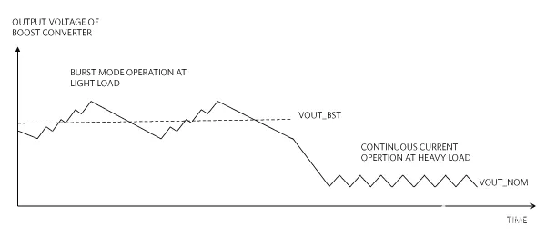
Figure 3. Light-load and heavy-load conditions for a boost converter.
Burst mode is a common power architecture for saving energy at light load. However, in optical sensing applications it can cause several issues, described in the following sections.
Burst-Mode Ripple
Burst-mode operation produces output voltage ripple (VOUT_BST) that is both low frequency and high amplitude. High-amplitude ripple causes inconsistent LED pulses, which leads to variable measurements. The low ripple frequency can be close enough to the sensor sampling frequency to become an in-band noise source that the sensor cannot adequately reject. An example burst-mode ripple measurement is shown in Figure 4: 120 mV ripple at 1.6 kHz for a 10 mA load.
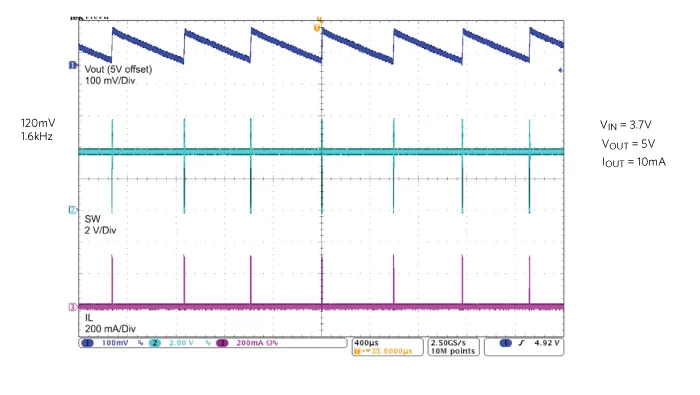
Figure 4. Burst-mode voltage ripple of a boost converter at 10 mA load current.
Unpredictable Noise During Mode Transitions
When a converter transitions from light-load operation to heavy-load operation during an LED pulse, unpredictable noise can appear on the output voltage, as shown in Figure 5. This again produces variable LED current and can make measurements unreliable.
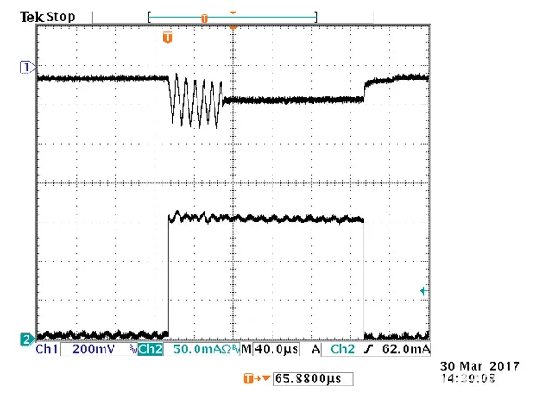
Figure 5. Noise during transitions between modes.
Slow Response to Load Transients
Typical LED pulse durations are on the order of several hundred microseconds. For consistent LED pulse current, the converter rise time in response to load transients must be as short as possible (<< 117 μs). Figure 6 shows that the transient response time of a typical boost converter can be as high as 50 μs, which is a significant fraction of an LED pulse duration.
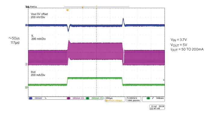
Figure 6. Response time for mode transitions.
Boost Converters for Optical Sensors
Some boost converters exhibit burst-mode behavior that is problematic for optical detection. The PMIC shown in Figure 8 includes a buck-boost converter designed to address these issues.
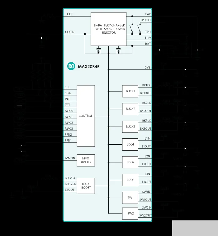
Figure 8. PMIC with a buck-boost converter.
As shown in Figure 9, the buck-boost converter in this device has much lower light-load ripple amplitude (≤ 20 mV), which yields more consistent LED current under light-load conditions than many other converters. It also operates at a higher frequency for a given load; for example, the switching frequency exceeds 100 kHz at loads as low as 5 mA. The higher operating frequency helps prevent switching noise from interfering with the measurement signal.
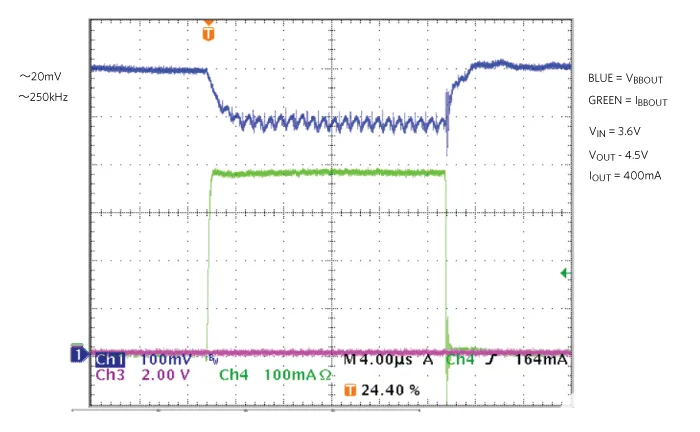
Figure 9. Lower-amplitude burst-mode ripple from the buck-boost converter.
In addition, the converter's load transient response time (< 3 μs) is significantly shorter than typical LED pulse durations (117 μs) and represents a one-order-of-magnitude improvement over the converters shown earlier. The faster response means that the converter's transient behavior will not limit the overall settling time of the optical measurement. Importantly, the transient response time and ripple characteristics are repeatable between pulses.
Measured Impact on Sensor SNR
Table 1 shows unfiltered SNR performance for a MAX86140 optical pulse oximeter and heart-rate sensor when powered by a conventional burst-mode converter versus the buck-boost converter in the PMIC. Under laboratory conditions (ideal reference SNR 89 dB), powering the sensor with a conventional burst-mode converter produced SNR degradation of up to 7 dB. When powered by the PMIC with the buck-boost converter, the sensor SNR approached the ideal laboratory conditions.
Table 1. Unfiltered SNR performance for the MAX86140 (dB)
| Photodiode Current (μA) | MAX20345 SNR (dB) | Competitor SNR (dB) |
|---|---|---|
| 1.5 | 80.74 | 77.96 |
| 15 | 88.20 | 81.55 |
| 32 | 88.78 | 81.20 |
System Integration
Besides the buck-boost regulator, the PMIC includes three buck regulators and three low-dropout linear regulators (LDOs), providing up to seven regulated voltages with ultra-low quiescent current. This allows the PMIC to power multiple peripherals and sensors, including a MAX86140 optical AFE, and a typical wearable microcontroller. The PMIC is offered in a 56-bump wafer-level package (WLP), 0.4 mm pitch, measuring 3.37 mm x 3.05 mm.
Summary
This design note reviewed how optical sensors measure metrics such as heart rate and blood oxygenation and why these sensors often require voltages above a single-cell lithium battery. Typical burst-mode boost converters can exhibit behavior that degrades SNR in optical sensing. A PMIC incorporating a buck-boost converter designed for optical sensing can greatly improve SNR performance in wearable and other IoT applications while maintaining low overall power consumption.