ALLPCB


Why 4 oz Copper Matters for High Current Motor Drivers
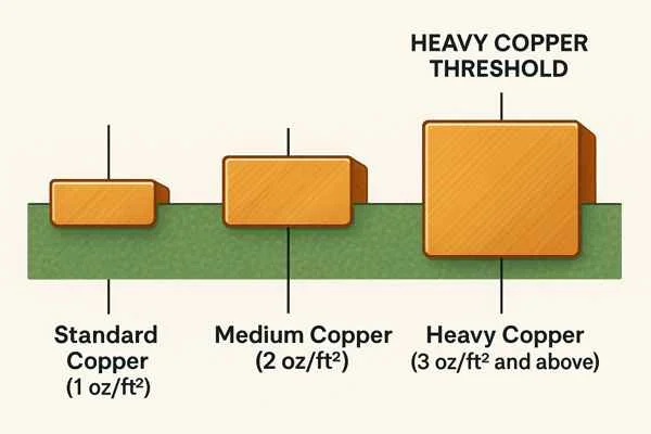
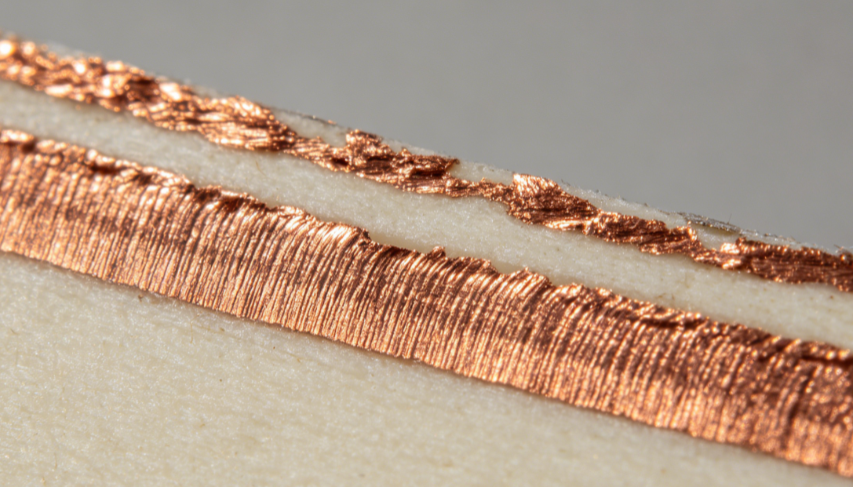
Copper weight of 4 oz per square foot corresponds to a nominal thickness of approximately 140 micrometers. This thickness reduces trace resistance compared with thinner foils, lowering I squared R losses under continuous or pulsed loads. In a high current motor driver, even modest resistance increases can generate localized heating that accelerates material degradation. Thicker copper distributes heat more effectively across the board surface and into attached heatsinks or chassis elements. Procurement teams and design engineers therefore evaluate 4 oz constructions when target currents approach or exceed 20 A per trace.
Industry specifications such as IPC-6012E define qualification requirements for rigid printed boards, including conductor thickness tolerances and plating integrity. These requirements help ensure that 4 oz copper layers maintain consistent performance after thermal cycling and mechanical stress.
Technical Principles of Current Carrying Capacity and Thermal Management
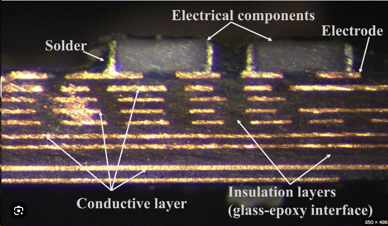
Trace current capacity depends on conductor width, thickness, allowable temperature rise, and the thermal conductivity of surrounding materials. Wider traces in 4 oz copper permit higher amperage before reaching the same temperature delta as narrower 1 oz traces. Internal layers benefit less from convection than external layers, so designers often route high current paths on outer surfaces or employ via stitching to parallel internal planes.
Thermal resistance from junction to ambient decreases when copper mass increases, because heat spreads laterally before transferring to the environment. Motor controllers experience both steady state loads and transient spikes during acceleration or braking. The additional thermal mass of 4 oz copper moderates temperature excursions, reducing peak stress on solder joints and component terminations.
Reliability under these conditions also depends on adhesion between copper and dielectric. IPC-A-600K outlines acceptance criteria for conductor integrity, including minimum copper thickness after processing and freedom from cracks or voids. Compliance with these criteria supports long term operation in environments subject to vibration and temperature cycling.
Practical Design and Manufacturing Considerations
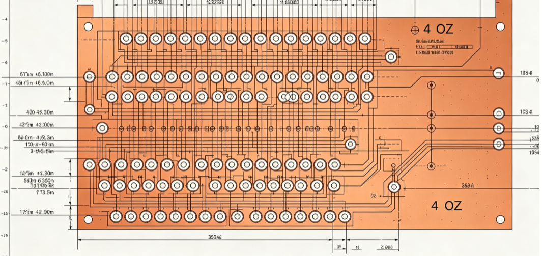
Effective layout begins with accurate current density calculations that account for both DC and ripple components typical of PWM motor drive. Trace widths are sized to keep temperature rise below 20 degrees Celsius or 30 degrees Celsius depending on application requirements. Adjacent traces carrying return currents should be placed to minimize loop inductance, which reduces voltage spikes that could stress semiconductors.
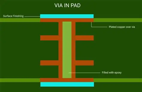
Via design requires attention when high current paths transition between layers. Multiple vias in parallel, each with sufficient plating thickness, distribute current and lower overall resistance. Copper plating in holes must meet minimum thickness specifications to avoid necking that could create hot spots.
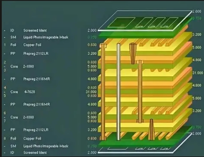
Material selection influences both electrical and mechanical performance. Laminates with appropriate glass transition temperature and coefficient of thermal expansion help maintain registration and prevent warpage during reflow or operation. Solder mask and surface finishes must withstand the higher processing temperatures sometimes associated with thicker copper boards.
Assembly and Reliability Practices
During assembly, controlled reflow profiles prevent excessive copper dissolution into solder while ensuring proper wetting. Thicker copper can act as a heat sink, requiring slightly extended dwell times or adjusted peak temperatures to achieve consistent joint quality. Post assembly inspection focuses on fillet formation and the absence of voids that could impede heat transfer.
Ongoing reliability benefits from design features that accommodate thermal expansion mismatch. Slots or relief patterns around high power components reduce mechanical stress transmitted to solder joints. Conformal coating, when applied, must be selected for compatibility with the board finish and operating environment to avoid trapping moisture that could initiate corrosion.
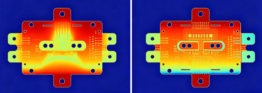
Troubleshooting common issues begins with verification of actual copper thickness on production samples. Undercut during etching or plating variability can reduce effective conductor cross section. Thermal imaging during loaded operation quickly identifies localized heating that indicates insufficient trace width or poor via placement. Corrective actions typically involve layout revisions rather than material changes once the board is fabricated.
Conclusion
Selecting 4 oz copper for motor controller PCBs provides a direct means to increase current capacity and improve thermal performance without enlarging board dimensions. Structured attention to trace geometry, via design, and material properties yields assemblies that meet demanding electrical and environmental requirements. Adherence to established qualification and acceptability standards supports consistent manufacturing outcomes and long service life.
FAQs
Q1: What advantages does a 4 oz copper PCB motor controller offer over standard constructions?
A1: A 4 oz copper PCB motor controller reduces resistive losses and improves heat spreading when driving motors at elevated currents. The thicker conductor allows narrower traces to carry the same amperage or wider traces to operate at lower temperature rise. This supports higher power density while maintaining PCB reliability motor control under continuous or cyclic loads.
Q2: How does copper thickness affect high current motor driver performance?
A2: Increased copper thickness lowers trace resistance, which decreases voltage drop and generated heat. In a high current motor driver, this translates to more efficient power delivery and reduced thermal stress on components and solder joints. Proper layout with 4 oz copper therefore contributes to overall system efficiency and longevity.
Q3: What design factors ensure reliability in 4 oz copper motor control PCBs?
A3: Trace width calculations, via stitching, and appropriate laminate selection are primary factors. Attention to plating thickness in holes and controlled thermal profiles during assembly further support reliability. These practices align with industry expectations for conductor integrity and thermal management in demanding applications.
Q4: Can 4 oz copper PCBs be used with standard assembly processes?
A4: Yes, provided reflow profiles account for the additional thermal mass of the copper. Inspection criteria remain consistent with established acceptability guidelines, and no special equipment beyond normal process controls is required when boards are designed correctly.
References
IPC-6012E — Qualification and Performance Specification for Rigid Printed Boards. IPC, 2017
IPC-A-600K — Acceptability of Printed Boards. IPC, 2020
JEDEC J-STD-020E — Moisture/Reflow Sensitivity Classification. JEDEC, 2014