Choosing the right PCB material is a critical step in ensuring the success of your printed circuit board project. With the help of DFM (Design for Manufacturability) software, you can streamline the process, avoid costly mistakes, and optimize your design for production. In this guide, we’ll walk you through the essentials of PCB material choice, explain which PCB material suits different applications, and show how DFM software for PCB projects can guide you to the right PCB choice. Let’s dive into a detailed exploration of these topics to help you boost your designs.
Why PCB Material Choice Matters for Your Project
The material you select for your printed circuit board directly impacts its performance, durability, and cost. A poor PCB material choice can lead to issues like signal loss, thermal failure, or manufacturing defects. On the other hand, the right material ensures your board operates reliably under specific conditions, whether it’s high-frequency signals or extreme temperatures. Pairing this decision with DFM software for PCB projects allows you to simulate and validate your choices before production, saving time and money.
In this blog, we’ll break down the key factors in selecting PCB materials and show how digital tools can simplify the process. Whether you’re a beginner or an experienced engineer, this guide to the right PCB choice will provide actionable insights for your next project.
Understanding the Basics of PCB Materials
PCB materials are the foundation of your board, typically consisting of a substrate (the core material) and conductive layers (usually copper). The substrate provides structural support and insulation, while the conductive layers form the electrical pathways. Choosing which PCB material to use depends on your project’s requirements, such as electrical performance, thermal management, and environmental conditions.
Common PCB materials include:
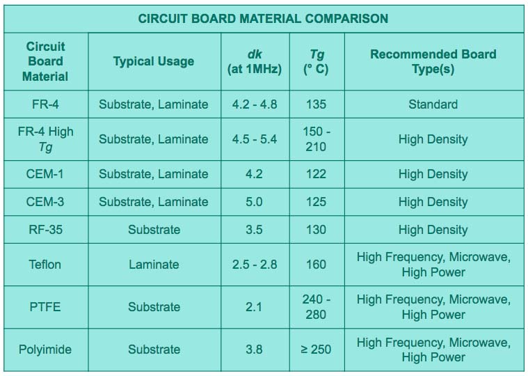
- FR-4: A widely used, cost-effective material made of woven fiberglass and epoxy resin. It’s suitable for most general-purpose applications with a dielectric constant (Dk) of around 4.5 at 1 MHz and good thermal resistance up to 130°C.
- High-Tg FR-4: An upgraded version of FR-4 with a higher glass transition temperature (Tg) of 170°C or more, ideal for designs exposed to higher heat.
- Polyimide: A high-performance material for flexible PCBs or high-temperature environments, withstanding up to 260°C and offering a Dk of about 3.5.
- Rogers Materials: Specialized laminates for high-frequency applications, with low dielectric loss (Df as low as 0.001) and stable Dk values (ranging from 2.2 to 10.2) for RF and microwave circuits.
- PTFE (Teflon): Used in high-frequency designs due to its low Dk (around 2.1) and minimal signal loss, though it’s more expensive.
Each material has unique properties that affect impedance, signal speed, and thermal conductivity. For instance, high-frequency designs often require materials with a low dissipation factor (Df) to minimize signal loss, while power electronics may prioritize high thermal conductivity to dissipate heat.

Factors to Consider in PCB Material Choice
When deciding which PCB material to use, several factors come into play. Let’s explore the most critical ones to ensure you make an informed decision.
1. Electrical Performance
The dielectric constant (Dk) and dissipation factor (Df) of a material determine how it handles electrical signals. For high-speed digital circuits or RF applications, you need materials with a stable Dk and low Df to maintain signal integrity. For example, a material with a Dk of 3.0 and Df of 0.002 can support signal speeds up to 10 GHz with minimal loss, whereas standard FR-4 might struggle beyond 1 GHz due to its higher Df of around 0.02.
2. Thermal Management
If your design operates in high-temperature environments or involves power-intensive components, thermal stability is key. Materials like High-Tg FR-4 or Polyimide can handle temperatures above 170°C without deforming, while standard FR-4 may fail at prolonged exposure to 130°C. Thermal conductivity, measured in W/m·K, also matters—some materials can dissipate heat at rates of 1.0 W/m·K or higher, protecting components from overheating.
3. Mechanical Strength and Flexibility
For rigid boards, mechanical strength ensures durability during assembly and use. For flexible or flex-rigid designs, materials like Polyimide offer the necessary bendability without cracking. Consider the coefficient of thermal expansion (CTE), which indicates how much a material expands with heat. A mismatch in CTE between layers can cause delamination or cracks during thermal cycling.
4. Cost and Availability
Balancing performance with budget is crucial. FR-4 is often the go-to choice for its low cost (around $0.50-$1.00 per square foot for standard grades) and wide availability. High-performance materials like PTFE or Rogers can cost 5-10 times more, so they’re typically reserved for specialized applications where performance justifies the expense.
5. Environmental and Regulatory Requirements
Some projects must comply with standards like RoHS (Restriction of Hazardous Substances) for lead-free designs. Additionally, if your PCB will be exposed to harsh conditions like humidity or chemicals, consider materials with high moisture resistance or specialized coatings.
How DFM Software for PCB Projects Simplifies Material Selection
Design for Manufacturability (DFM) software is a powerful tool that helps engineers optimize their designs for production. When it comes to PCB material choice, DFM software for PCB projects can analyze your design parameters and recommend materials that meet both performance and manufacturing requirements. Here’s how it works and why it’s a game-changer.
1. Simulation and Validation
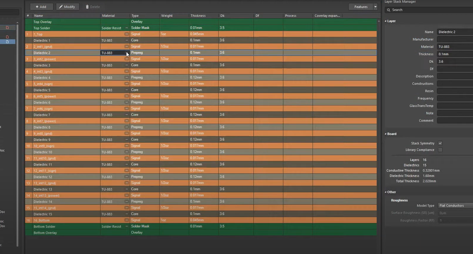
DFM tools allow you to simulate how different materials will perform in your design. For example, you can input parameters like signal frequency (e.g., 5 GHz) and board thickness (e.g., 1.6 mm), and the software will calculate impedance values and signal loss for various materials. This helps you identify the best option without physical prototyping, which can save weeks of development time.
2. manufacturability Checks
DFM software evaluates whether your chosen material aligns with manufacturing capabilities. It flags issues like incompatible layer stackups or materials that are difficult to source or process. For instance, if a high-frequency material requires specialized etching processes that increase costs, the software can suggest alternatives with similar performance at a lower price point.
3. Cost Optimization
By integrating material databases and cost models, DFM tools help you balance performance and budget. They can estimate the cost per board based on material selection, layer count, and volume, allowing you to make data-driven decisions. For a mid-range project, switching from a premium material to a high-Tg FR-4 might reduce costs by 30% without sacrificing reliability.
4. Error Prevention
Human error in material selection can lead to costly redesigns. DFM software minimizes this risk by cross-referencing your design against industry standards and material properties. If a material’s CTE is too high for your thermal profile, the tool will alert you before you finalize the design.

Step-by-Step Guide to the Right PCB Choice with DFM Software
Now that you understand the importance of PCB material choice and the role of DFM tools, let’s walk through a practical guide to making the right decision for your project.
Step 1: Define Project Requirements
Start by listing the key requirements of your design. What are the operating frequencies? Will the board face high temperatures or mechanical stress? Are there budget constraints? For example, a wireless communication device might need a material with a Dk below 3.0 for signals at 2.4 GHz, while a power supply board prioritizes thermal conductivity above 0.8 W/m·K.
Step 2: Shortlist Potential Materials
Based on your requirements, narrow down a list of materials. Use online resources or material datasheets to compare properties like Dk, Df, Tg, and cost. For general-purpose designs, FR-4 might suffice, while high-frequency projects could shortlist PTFE or specialized laminates.
Step 3: Input Data into DFM Software
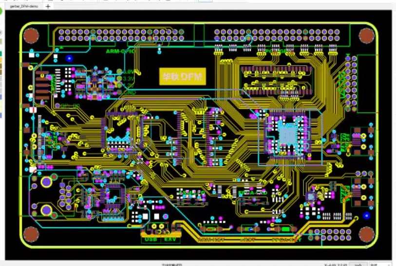
Enter your design specifications into the DFM tool, including layer count, board dimensions, and performance needs. Upload your schematic or layout files if the software supports it. The tool will analyze the data and suggest materials that match your criteria.
Step 4: Simulate and Compare Results
Run simulations to see how each material performs. Check metrics like signal integrity, thermal distribution, and impedance matching. For instance, if a material shows a signal loss of 0.5 dB at your target frequency, but another offers 0.2 dB, the latter might be worth the slight cost increase.
Step 5: Review Manufacturability and Cost
Use the DFM software to confirm that your chosen material is compatible with manufacturing processes and fits your budget. Adjust your selection if the tool flags potential issues like long lead times or high processing costs.
Step 6: Finalize and Document
Once you’ve validated the material with the DFM tool, finalize your choice and document the decision in your project files. Include simulation results or software recommendations as justification for future reference.
Common Mistakes to Avoid in PCB Material Selection
Even with the best tools, mistakes can happen. Here are some pitfalls to watch out for when deciding which PCB material to use.
- Overlooking Thermal Needs: Choosing a material with a low Tg for a high-heat application can lead to board failure. Always match the material’s thermal properties to your operating conditions.
- Ignoring Frequency Requirements: Using standard materials for high-frequency designs can cause signal degradation. Ensure the Dk and Df are suitable for your signal speeds.
- Focusing Only on Cost: Opting for the cheapest material might save money upfront but can result in performance issues or manufacturing delays. Balance cost with quality.
- Skipping DFM Analysis: Not using DFM software for PCB projects can lead to unnoticed compatibility issues. Leverage these tools to catch problems early.
Benefits of Using DFM Software for Long-Term Success
Integrating DFM software into your workflow offers benefits beyond material selection. It reduces time-to-market by identifying issues before production, lowers costs by optimizing designs, and improves product reliability through thorough simulations. For instance, companies using DFM tools often report a 20-30% reduction in design iterations, translating to significant savings in both time and resources.
Moreover, DFM software keeps your designs aligned with industry standards, ensuring that your PCBs meet regulatory and performance expectations. This is especially valuable for complex projects involving multilayer boards or high-density interconnects (HDI), where material choice plays an even bigger role.
Conclusion: Elevate Your PCB Designs with Smart Material Choices
Selecting the right PCB material is a foundational step in creating high-performing, reliable circuit boards. By understanding which PCB material fits your project’s needs and leveraging DFM software for PCB projects, you can make informed decisions that enhance manufacturability and performance. This guide to the right PCB choice has covered the essentials—from material properties and selection factors to the practical use of digital tools—so you’re equipped to tackle your next design with confidence.
Start by defining your project requirements, use DFM tools to simulate and validate your options, and avoid common pitfalls in material selection. With these strategies, you’ll boost your designs and achieve better outcomes in every PCB project. Trust in the power of informed choices and advanced software to take your engineering to the next level.

 ALLPCB


