 ALLPCB


For PCB design engineers, selecting the right BGA (Ball Grid Array) socket is critical to ensuring the performance, reliability, and cost-effectiveness of a project. With numerous factors to consider, such as BGA socket types, pitch, materials, reliability, cost, impedance matching, thermal management, and footprint, making an informed choice can be complex. This guide offers a detailed roadmap to help you navigate these considerations and choose the best BGA socket for your design needs.
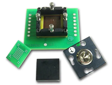
At its core, a BGA socket is a specialized connector that allows a BGA package—an integrated circuit with an array of solder balls on its underside—to be mounted onto a printed circuit board (PCB) without permanent soldering. This flexibility is invaluable for testing, prototyping, and applications requiring easy replacement. In the sections below, we’ll dive deep into every aspect of BGA socket selection to equip you with actionable insights for your next project.
What Is a BGA Socket and Why Does It Matter?
A BGA socket serves as an interface between a BGA package and a PCB, enabling a secure yet removable connection. Unlike direct soldering, which permanently attaches the BGA to the board, a socket allows for repeated insertion and removal of the chip. This is especially useful during development phases, debugging, or when upgrading components in high-value systems.
Choosing the right BGA socket impacts signal integrity, thermal performance, and overall system reliability. A poorly matched socket can lead to signal loss, overheating, or mechanical failure, costing time and resources. By understanding key factors like BGA socket pitch, materials, and thermal management, you can optimize your design for both performance and longevity.
Key Factors in BGA Socket Selection
Selecting a BGA socket involves evaluating multiple parameters to match your project’s requirements. Below, we break down the critical aspects every PCB design engineer should consider.
1. BGA Socket Types
BGA sockets come in various types, each suited to specific applications. Understanding these types helps narrow down your options based on whether you’re focusing on prototyping, production testing, or final assembly.
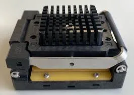
- Clamshell Sockets: These sockets feature a hinged lid that clamps down on the BGA package, ensuring firm contact. They are ideal for burn-in testing and high-volume production environments due to their durability and ease of use.
- Open-Top Sockets: Designed for quick insertion and removal, open-top sockets are perfect for prototyping and debugging. They allow easy access to the BGA package but may offer less secure contact compared to clamshell designs.
- Zero Insertion Force (ZIF) Sockets: ZIF sockets minimize the risk of damage during insertion by requiring no force to place the BGA package. They are often used in delicate testing scenarios but can be more expensive.
- Compression Sockets: These rely on a compressive force to connect the BGA to the PCB, often using elastomeric materials. They are common in high-frequency applications due to their excellent signal integrity.
Choosing the right type depends on your project’s stage and needs. For instance, if you’re in early development, an open-top socket might save time during frequent chip swaps. For production testing, a clamshell socket could provide the reliability needed for repeated cycles.
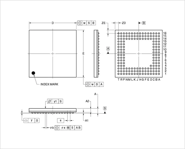
2. BGA Socket Pitch
The pitch of a BGA socket refers to the distance between the centers of adjacent solder balls or contact points, typically measured in millimeters. Common BGA socket pitch sizes include 0.5mm, 0.8mm, 1.0mm, and 1.27mm. Matching the socket pitch to your BGA package is non-negotiable—any mismatch will prevent proper connection.
Smaller pitches, like 0.5mm, allow for higher pin density, which is crucial for compact, high-performance designs. However, they require precise PCB layouts and advanced manufacturing capabilities. Larger pitches, such as 1.27mm, are easier to work with but may limit the number of connections in a given area. Always verify the pitch specification of your BGA package before selecting a socket to avoid costly redesigns.
3. BGA Socket Materials
The materials used in a BGA socket affect its durability, conductivity, and thermal performance. Common materials include:
- Body Materials: High-temperature plastics or composites are often used for the socket body to withstand soldering processes and operational heat. Look for materials with high thermal stability, such as liquid crystal polymer (LCP), which can handle temperatures up to 260°C.
- Contact Materials: Contacts are typically made from beryllium copper or phosphor bronze, often plated with gold or nickel to enhance conductivity and resist corrosion. Gold plating, for instance, ensures low contact resistance, which is vital for high-speed signals.
Material selection should align with your application’s environmental conditions. For harsh environments, prioritize corrosion-resistant materials. For high-frequency designs, opt for contacts with superior conductivity to minimize signal loss.
4. BGA Socket Reliability
Reliability is a cornerstone of BGA socket selection, as it directly impacts the longevity and performance of your design. A reliable socket must maintain consistent electrical contact over thousands of insertion cycles, resist wear, and operate under varying temperatures.
Look for sockets rated for high cycle counts—some premium models can handle over 10,000 insertions without degradation. Additionally, consider the socket’s ability to withstand thermal cycling (e.g., -55°C to 125°C) without cracking or losing contact. Reliability data from manufacturers, such as mean time between failures (MTBF), can guide your decision. For mission-critical applications like aerospace or medical devices, investing in high-reliability sockets is a must.
5. BGA Socket Cost
Cost is always a factor in PCB design, and BGA sockets vary widely in price based on type, materials, and performance specifications. Basic open-top sockets might start at a few dollars per unit, while advanced ZIF or compression sockets for high-frequency applications can cost $50 or more each.
Balancing cost with performance is key. For prototyping, a lower-cost socket may suffice since durability isn’t a primary concern. However, for production or high-stakes testing, investing in a pricier, more reliable socket can save money in the long run by reducing failures and downtime. Always evaluate the total cost of ownership, including potential rework expenses, when making your choice.
6. BGA Socket Impedance Matching
Impedance matching is crucial for high-speed digital and RF applications, where signal integrity can make or break performance. A BGA socket must minimize impedance discontinuities to prevent signal reflections and loss. Poor impedance matching can result in data errors or reduced speeds, especially in systems operating at frequencies above 1 GHz.
Look for sockets designed with controlled impedance, often specified by manufacturers in ohms (e.g., 50 ohms for many RF applications). Compression sockets, for instance, often provide better impedance matching due to their uniform contact pressure. Additionally, ensure that the socket’s design complements your PCB trace layout to maintain consistent impedance throughout the signal path.
7. BGA Socket Thermal Management
Thermal management is a growing concern as BGA packages become denser and more power-intensive. A socket must dissipate heat effectively to prevent overheating, which can degrade performance or damage components. Poor thermal management can lead to junction temperatures exceeding safe limits, often above 85°C for many ICs.
Choose sockets with built-in thermal pathways, such as metal heat spreaders or designs that allow airflow around the BGA package. Some high-performance sockets are compatible with external heatsinks or thermal pads to enhance cooling. Always check the thermal resistance rating (e.g., °C/W) provided by the manufacturer to ensure it meets your design’s heat dissipation needs.
8. BGA Socket Footprint
The footprint of a BGA socket refers to the space it occupies on the PCB, including the layout of contact pads and any additional mounting areas. A socket’s footprint must match the BGA package and fit within your board’s design constraints. Mismatched footprints can lead to alignment issues or wasted board space.
When designing your PCB, use the socket manufacturer’s recommended footprint layout, often provided in datasheets or CAD files. Pay attention to pad sizes, spacing, and any keep-out zones for mounting hardware. For high-density designs, opt for sockets with minimal footprint overhead to maximize board real estate. Additionally, consider via placement and routing challenges, as BGA sockets often require complex multilayer PCB designs to accommodate all connections.
How to Choose the Right BGA Socket for Your Project
With all these factors in mind, follow these steps to select the ideal BGA socket for your PCB design:
- Define Your Application: Determine whether you’re in prototyping, testing, or production. This sets the tone for socket type and durability needs.
- Match Specifications: Ensure the socket’s pitch, footprint, and electrical ratings align with your BGA package and PCB layout.
- Prioritize Performance Needs: Focus on impedance matching and thermal management if you’re working on high-speed or power-intensive designs.
- Balance Cost and Reliability: Weigh the upfront cost against long-term reliability to avoid expensive failures or rework.
- Consult Manufacturer Data: Use technical datasheets and support resources to verify compatibility and performance metrics.
By systematically addressing these points, you can confidently select a socket that enhances your design’s performance and reliability.
Common Challenges and Solutions in BGA Socket Selection
Even with careful planning, challenges can arise during BGA socket selection. Here are some common issues and how to tackle them:
- Challenge: Signal Integrity Issues
Solution: Opt for sockets with controlled impedance and minimal contact resistance. Simulate signal paths during the design phase to identify potential problems early. - Challenge: Thermal Overheating
Solution: Integrate thermal management features like heatsinks or select sockets with low thermal resistance. Ensure adequate airflow in your system design. - Challenge: Footprint Mismatches
Solution: Double-check footprint dimensions against manufacturer recommendations before finalizing your PCB layout. Use design software to validate alignment.
Conclusion: Making an Informed BGA Socket Choice
Selecting the right BGA socket is a pivotal decision for PCB design engineers, influencing everything from signal integrity to thermal performance and project costs. By carefully evaluating BGA socket types, pitch, materials, reliability, cost, impedance matching, thermal management, and footprint, you can ensure your design meets both technical and budgetary goals.
This comprehensive guide has walked you through each critical factor, providing practical insights and solutions to common challenges. Armed with this knowledge, you’re well-equipped to make informed decisions that optimize your PCB designs for success. Whether you’re prototyping a new product or scaling up for production, the right BGA socket can be a game-changer in achieving peak performance.


