ALLPCB


1 Hardware Platform
1.1 Zynq-7045 / Zynq-7100 Evaluation Board
TLZ7xH-EVM is an evaluation board based on the Xilinx Zynq-7000 series XC7Z045 / XC7Z100 heterogeneous SoC. The processor subsystem (PS) integrates a dual-core ARM Cortex-A9, and the programmable logic (PL) is based on Kintex-7 28 nm architecture. The evaluation board consists of a core module and a carrier board. The core module has undergone PCB layout and temperature testing and is suitable for a range of industrial applications.
The TLZ7xH-EVM provides a rich set of interfaces: dual Gigabit Ethernet, four SFP+ optical ports, dual CameraLink, HDMI, FMC, PCIe, USB, and Micro SD, among others, to support rapid product evaluation and technical prototyping.
1.2 AD9361 Software Defined Radio Module
AD-FMCOMMS3-EBZ is a module based on the AD9361 RF transceiver IC. The AD9361 is a high-performance, highly integrated RF transceiver designed for SDR architectures. It is suitable for wireless infrastructure, defense electronics, RF test equipment and instruments, and general SDR platforms. The device integrates RF front ends with a flexible mixed-signal baseband, includes a frequency synthesizer, and provides configurable digital interfaces for processors or FPGAs. Its programmability and wideband capability make it suitable for a variety of transceiver applications.
Main features:
- Integrated 12-bit DAC and ADC RF 2×2 transceiver
- TX range: 47 MHz to 6.0 GHz
- RX range: 70 MHz to 6.0 GHz
- Supports both TDD and FDD operation
- Tunable channel bandwidth: 200 kHz to 56 MHz
- Dual-channel receiver: 6 differential or 12 single-ended inputs
- Excellent receiver sensitivity, noise figure about 2 dB (800 MHz LO)
- RX gain control:
- Real-time monitoring and control signals for manual gain
- Independent automatic gain control
- Dual transmitters: 4 differential outputs
- High-linearity, wideband transmitter:
- TX EVM: <= -40 dB
- TX noise: <= -157 dBm/Hz noise floor
- TX monitor: dynamic range >= 66 dB, accuracy = 1 dB
- Integrated fractional-N frequency synthesizer
- Maximum LO step: 2.4 Hz
- Multi-device synchronization
- CMOS / LVDS digital interface
Applications:
- General-purpose designs for SDR applications
- MIMO radios
- Point-to-point communication systems
- Small cell and microcell base stations
- Wi-Fi
- ISM
- Aerospace
- Public safety
- Smart grid
2 Example Demonstration
2.1 Development Environment
This example uses the following development environment:
- Windows host: Windows 7 64-bit or Windows 10 64-bit
- Virtual machine: VMware 14.1.1
- Linux development: Ubuntu 18.04.5 64-bit
- PetaLinux: 2017.4
- Xilinx Vivado: 2017.4
- Xilinx SDK: 2017.4
- Software components:
- ADI IIO Oscilloscope: ADI's IIO Oscilloscope provides a spectrum-analyzer-like interface for SDR devices such as Pluto. It can display time domain, frequency domain, constellation, and cross-correlation data and can be configured via IIO to display sampled signals.
- Cygwin: A POSIX-like environment for Windows that enables using cross-compilers and UNIX-like toolchains on Windows hosts.
2.2 Example Functionality
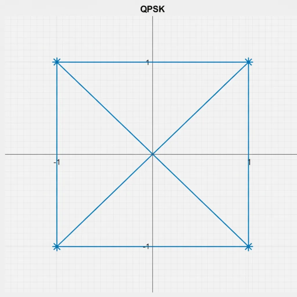
The example builds an RF transceiver test platform using the TLZ7xH-EVM evaluation board and the AD-FMCOMMS3-EBZ module. It demonstrates QPSK (Quadrature Phase Shift Keying) digital modulation and FM radio reception.
QPSK is a common digital modulation method used in satellite communications, offering efficient spectral use and robustness to interference. Offset QPSK (O-QPSK) is often used to reduce amplitude variation.
In QPSK, the carrier can take four discrete phase states, and each carrier phase conveys 2 binary symbols. The basic steps in QPSK digital demodulation include ADC conversion, decimation or interpolation, matched filtering, and recovery of clock and carrier.
Digital modulation is often described using a constellation diagram, which defines:
- Signal distribution
- Mapping between modulation symbols and digital bits
For QPSK (M = 4), the four carrier phases are typically 45°, 135°, 225°, and 315°. Binary input data is grouped into pairs of bits, yielding four possible combinations: 00, 01, 10, 11. Each pair maps to one constellation symbol. The receiver determines the transmitted bits by comparing the received carrier phase to the constellation.
The constellation axes are: the horizontal X axis for the in-phase component and the vertical Y axis for the quadrature component. For each constellation point:
- The projection on the X axis gives the peak amplitude of the in-phase component.
- The projection on the Y axis gives the peak amplitude of the quadrature component.
- The vector from the origin to the point represents the combined peak amplitude.
- The angle between the vector and the X axis is the signal element phase.
In this example, a MicroBlaze processor configures the AD-FMCOMMS3-EBZ module's AD9361 via AXI SPI and AXI GPIO, and data transfer is handled through ADI AXI AD9361 IP for transmit and receive. Data movement to and from DDR is performed via the ADI AXI DMA IP, with DDR driven by a MIG IP.
2.3 Example Testing
Testing is performed on the TLZ7xH-EVM Linux system. Prepare a system boot card using the case-specific image. The example source code is provided with the evaluation board and module.
2.3.1 QPSK Digital Debug Test
Connect the module TX1A and RX1A to 2.4 GHz antennas and install the module on the board FMC connector. Connect the board to a router with an Ethernet cable. Use jumper caps to set the BANK voltage to 2.5 V.
Use the IIO Oscilloscope to view the constellation. Both line-style and point-style constellation displays are available. Adjusting the antenna position will change the observed constellation.
2.3.2 FM Reception Test
Connect RX1A to an FM antenna and install the module on the board FMC connector. Connect Ethernet to the router. Use jumper caps to set the BANK voltage to 2.5 V. Plug a USB sound card into the board USB HOST port and connect headphones to the USB sound card output.
In the IIO Oscilloscope interface, right-click in an empty area and select "Single Tone Markers". The current FM tune frequency can be viewed in the Markers window. When the detected frequency matches the desired frequency, stop spectrum acquisition to avoid affecting FM reception.
Run the following command on the target board to play FM audio. Replace 102.7 with the detected frequency as appropriate:
Target# iio_fm_radio_play 102.7
Exit FM playback with Ctrl + C.