 My Message
 Suggestions


We know there may be some problems in the data exchange of each sub-module of the circuit system, so the signal cannot be normally and circulated in high quality.
For example, sometimes the working sequence of the circuit sub-modules is deviated (such as CPU and peripherals) or the respective signal types are inconsistent (such as the sensor detects the optical signal), etc., then we should consider the corresponding interface to deal with this problem well.
The following is a description of the key points of the seven commonly used interface types in circuit design:
1. TTL level Interface
This type of interface is basically a cliche. Starting from college to learn analog circuits and digital circuits, for general circuit design, the TTL level interface basically can't take off the "dry system"!
Its speed is generally limited to 30MHz. This is because there are several pF input capacitors at the input of the BJT (constituting an LPF). If the input signal exceeds a certain frequency, the signal will be "lost". Its driving capacity is generally up to tens of milliamps. The signal voltage for normal operation is generally high, and if it is close to the ECL circuit with a lower signal voltage, a more significant crosstalk problem will occur.
2. CMOS Level Interface
We are no stranger to it, and we often deal with it. Some semiconductor features about CMOS don't have to be lost here. What many people know is that CMOS's power consumption and anti-interference ability are much better than TTL under normal conditions.
Little-known is that at high switching frequencies, the CMOS series actually consumes more power than TTL. As for why, please ask about semiconductor physic theory.
Since the operating voltage of CMOS can be very small at present, some FPGA cores work at even close to 1.5V, which makes the noise margin between levels much smaller than TTL, thus increasing the voltage fluctuation. The signal is judged incorrectly. It is well known that the input impedance of a CMOS circuit is very high, so its coupling capacitance can be small without using a large electrolytic capacitor.
Since the CMOS circuit usually has a weak driving capability, it is necessary to perform TTL conversion before driving the ECL circuit. In addition, when designing a CMOS interface circuit, care should be taken to avoid excessive capacitive loading, otherwise the rise time will be slower and the power consumption of the driver device will increase (because the capacitive load does not consume power).
3. ECL Level Interface
This is an old friend inside the computer system! Because its speed "runs" fast enough, it can even run to hundreds of MHz! This is because the BJT inside the ECL is not saturated when it is turned on, which can reduce the turn-on and turn-off time of the BJT, and the working speed can naturally be raised.
But, this is a price! Its fatal injury: power consumption is bigger! The EMI problem caused by it is worth considering, and the anti-interference ability is not much better. If anyone can compromise these two factors, then he or she should make a fortune.
It should also be noted that a general ECL integrated circuit requires a negative power supply, that is, its output voltage is negative, and a special level shift circuit is required.
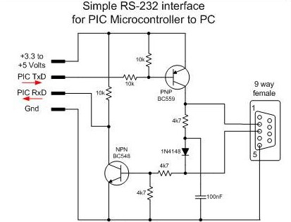
4. RS-232 Level Interface
No one who knows the basics of playing electronic technology knows it (unless he or she is just "outsider" of electronic technology). It is a low-speed serial communication interface standard.
It should be noted that its level standard is a bit "abnormal": high level is -12V, and low level is +12V. So, when we try to communicate with peripherals through a computer, a level-shifting chip MAX232 is naturally indispensable. But we have to be aware of some of its shortcomings, such as slower data transmission speeds and shorter transmission distances.
5. Optical Isolation Interface
Photoelectric coupling is the coupling and transmission of electrical signals based on optical signals. Its "benefit" is to achieve electrical isolation, so it has excellent anti-interference ability. Under the condition that the circuit operates at a high frequency, basically only the high-speed isolated interface circuit can meet the needs of data transmission.
Sometimes in order to achieve high voltage and high current control, we must design and use optically isolated interface circuits to connect these low-level, low-current TTL or CMOS circuits as described above, because the input and output circuits of the optically isolated interface It can withstand a high voltage of several thousand volts, which is enough for general applications.
In addition, the input part and the output part of the optical isolation interface must be independent power sources respectively, otherwise there is still electrical connection, which is not called isolation.
6. Coil Coupling Interface
Its electrical isolation characteristics are good, but the allowed signal bandwidth is limited. For example, transformer coupling, its power transmission efficiency is very high, the output power is basically close to its input power, therefore, for a step-up transformer, it can have a higher output voltage, but can only give a lower Current.
In addition, the high-frequency and low-frequency characteristics of the transformer are not optimistic, but its biggest feature is that impedance transformation can be realized. When matched, the load can obtain enough power. Therefore, the transformer coupling interface is in the power amplifier circuit design.


