 My Message
 Suggestions


Over-voltage and over-current protection circuit for use with the C-BISCUIT platform's main computer, the Wandboard.
The C-BISCUIT Series
- C-BISCUIT: A Robotics Platform for the Hacker and Hobbyist
- C-BISCUIT: Design Choices and Justification
- C-BISCUIT Power: 5V 3A Buck Regulator for Wandboard
- C-BISCUIT Power: Crowbar Protection Circuit for 5V Regulator
- C-BISCUIT: The Brains of the Operation
- C-BISCUIT Power: Assembly and Testing of Regulator and Crowbar Circuits
- C-BISCUIT: Monitoring Your Robot’s Health
- C-BISCUIT: Robot System Architecture
- C-BISCUIT: Schematic Design for the RCB—Microcontroller, Motor Controller
- C-BISCUIT: Schematic Design for the RCB—Power, Stepper
- C-BISCUIT: Layout and Assembly for the Robot Control Board
- C-BISCUIT: System Integration and Testing

An overview of the C-BISCUIT power systemIntroduction
In the previous C-BISCUIT article, we designed a DC-DC power converter to regulates our ~11V battery voltage to a nice, clean 5.0 V. In an ideal world, this is all we'd ever need but in the real world, we need to consider protection circuitry in the event of upsets, namely over-voltage and over-current conditions. One way of doing this is with something called a "crowbar" circuit.

A generic 9.1 V, 250 mA crowbar circuit that uses a silicon controlled rectifier, or SCR, to short the output terminals
If the input voltage to the circuit reaches a certain threshold (9.1 V in the example above), a Zener diode breaks down and causes either a TRIAC or SCR to short power and ground... as if you threw a crowbar across the terminals.This forces a lot of current through the device but immediately lowers the voltage. An inline fuse will then electrically disconnect the load (the Wandboard in our case) from the supply. In the case of an SCR, when the Zener diode breaks down, a voltage appears on the gate terminal of the SCR. If this is above the SCR's gate activation voltage, the device turns on.
Our Crowbar Circuit

The one that we're implementing is a little different. We're incorporating an adjustable Zener diode (technically an "adjustable precision Zener shunt regulator") from TI called the LM431 and a TRIAC as opposed to an SCR. The diode breaks down whenever the voltage at the reference input reaches 2.5 V. This means it can be set to pretty much any level with a simple voltage divider. R1 and R2 were chosen such that the limit voltage is just about 6 V.
You'll notice that the resistor and the Zener are reversed in this implementation. That's due to the fact that TRIAC and the SCR don't trigger in the same way. The LM431's cathode current when off is about 1 uA. This means there is a very small voltage drop across R4, essentially keeping MT1 and the gate of the TRIAC at the same voltage. When the trigger voltage is reached and the Zener breaks down, current begins to flow through R4, causing a larger drop across it.
This puts the TRIAC into what's known as quadrant 3 operation, since both MT2 and the gate are at lower potentials than MT1. Essentially, a small amount of current flows from MT1 to the gate which causes a large amount of current to flow from MT1 to MT2. If this is more than a few milliamps, the TRIAC "latches" (latch current) and stays conducting until that current is less than a quantity known as the holding current.
When the TRIAC conducts, a 3A automotive fuse will blow, protecting the circuit. There's also a handy, dandy LED to let you know if the fuse has blown or not.
Simulation
With most analog circuits, it's a very wise idea to simulate the design before prototyping. SPICE is the de facto tool for this and comes in many different flavors and variants. Essentially a numerical differential equation solver for circuit primitives, SPICE can be used to give you a good approximation of real-world circuit performance. However, non-trivial circuits involving complex ICs can often be challenging to model. LTSpice IV is a popular simulator and most LT parts have free SPICE models available for download. I wanted to simulate the TRIAC trigger circuit and set out to find a model for the Zener diode. TI doesn't provide any models for the LM431, but they do offer several for the TL431, which should have similar circuit behavior.
After attempting to adapt the HSPICE and PSPICE models to LTSpice with lackluster results, I ended up downloading TINA-TI (TI's flavor of SPICE simulator) and using the encrypted TINA module of the TL431. My transient analysis file is located in the ZIP file at the bottom of the page in thesimdirectory.

TINA schematic
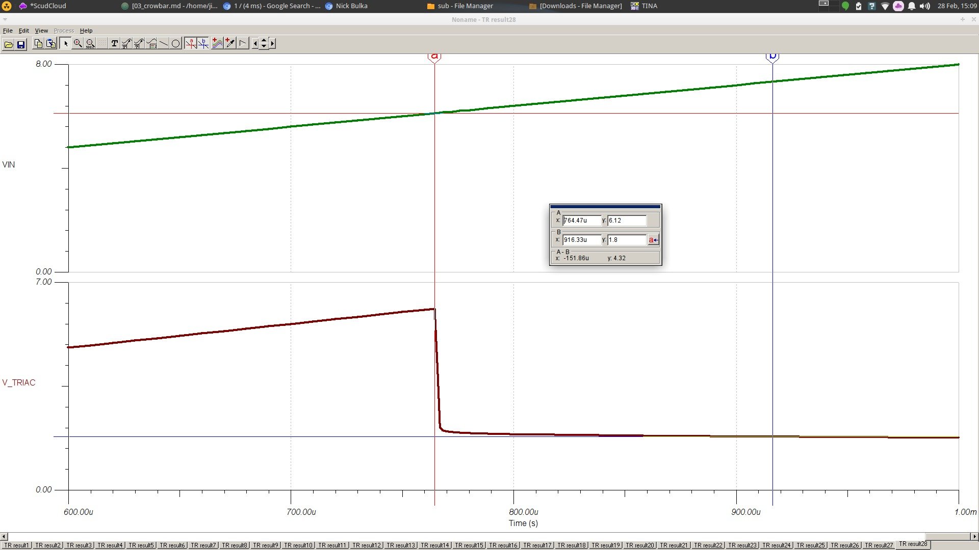
1 ms transient analysis simulation (click for full size)
From the transient analysis, we can see that once the input voltage reaches just about 6 V, the Zener breaks down and the TRIAC gate voltage falls to 1.8 V this is below the gate threshold voltage for Q3 operation and so we can safely assume that the TRIAC will start conducting and latch until the fuse blows.
Layout
This circuit is supposed to be small and unobtrusive. It's skinny and long (13mm x 37mm), which makes it possible to be soldered inline between the regulator and the Wandboard with some protective heat shrink over it. The LED is technically optional but you can cut a small slit in the heatshrink for the LED to peek out of to give you a visual indicator of connectivity.
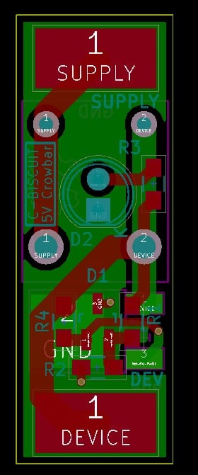
PCB layout in KiCad
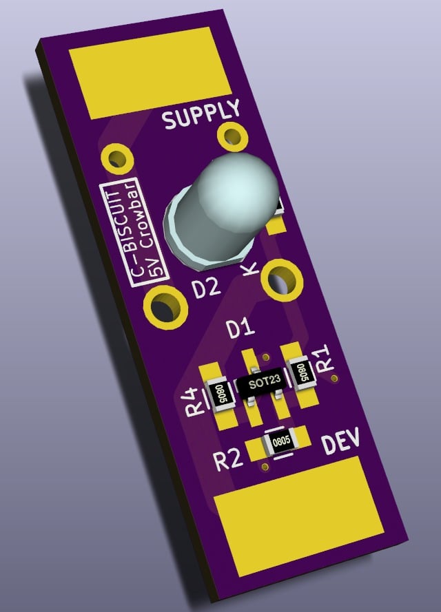
Rendering (Top)

Rendering (Bottom)
Design Files
All the design files are available on Github or as a self-contained ZIP file below. Included in the ZIP file are the schematic, layout, and BOM files as well as part libraries and datasheets.
Download Code
Moving Forward
The last component to be designed for the power system is a power distribution board that the batteries connect to. It will allow hot swapping the batteries without having to shut down anything and will contain monitoring circuitry for both battery voltage and current that can talk over a standard interface like SPI or I2C. We also need to get the previously designed boards populated and test their functionality. After that, the software design will begin. See you then... same bat time, same bat channel!


Augus
1/3/1900 12:00:00 AM
You are a genuis!