 My Message
 Suggestions


To complete today’s part of the microcontroller tutorial – I have doubted myself, I’ve burned my finger and I’ve received a surprise bill from the customs.
But all in all, I’m very happy with the result. I made it work. And I love the feeling I get when I make something work!
We are now at part 5, the final part, of the microcontroller tutorial. Up until now we have learned:
What a microcontroller is
How to select a microcontroller
How to design a circuit with the microcontroller
How to create a circuit board from our circuit
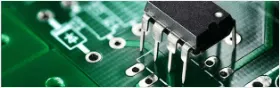
I have just received the boards I ordered in the previous part, and today we are going to solder the board and program it.

Look at this beautiful board, just waiting to be soldered.
Soldering The Board
To solder the board – I am going to use my old Ersa 30 soldering iron. The tip of it is a bit big, so it’s really not the ideal tool to use.
But it’s what I have on my desk right now.
And it’s also a way for me to show you, that you don’t need any fancy equipment to make this circuit.
You can make this circuit at home.

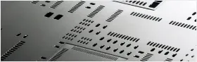
Because I wanted to put everything on one side, I chose to use mostly SMD (Surface Mount Device) components when I designed the circuit board.
So to solder this, I’m going to use the techniques from my smd soldering article.
Soldering the Microcontroller Chip
Since the microcontroller chip was the most difficult thing to solder, I started out with that one.
First, I added some solder to one corner pad. I placed the chip carefully, using a pair of tweezers. And I made sure that all the pins were placed correctly over their pads.
Then, while holding the chip in place with the tweezers, I placed the tip of my soldering iron onto the pin and pad of the corner where I already added solder – making the solder melt.
I removed the tip, and let the solder cool for a second. The chip was in place. Now, all I needed to do was to apply a bit on solder onto each of the pins, to make them stick to the pads on the board.

This was a clumsy process with the thick tip of my soldering iron. But, by keeping my cool and being patient – I was able to solder all the pins onto their pads. We only need a tiny bit of solder each pin.
As you can see from the picture above, soldering with the large-tip soldering iron was a bit messy. But it doesn’t matter – as long as it works.
Soldering the Other Components
After I’d managed to solder the chip, the other components were easy. I might not have gotten them perfectly aligned, but it wasn’t that bad either.

Testing the Circuit
The ATmega32U2 chip comes with a pre-programmed boot-loader that should make it appear as a USB device when plugged in to a computer.
After everything was soldered, I SHOULD have inspected the solder joints closely with a USB Microscope or something. It’s smart, because if there are any short-circuits caused by a tiny little solder blob somewhere, we could damage our circuit.
But I didn’t have one nearby – and I was super excited to see if it worked. I’m kind of like a child waiting to open my presents on christmas in this situation. I can’t always make myself do what is smart to do. I’m just too excited to see if it works. So instead I just looked extra carefully at the USB pins, to see if they at least seemed to be properly soldered.
I plugged it into my USB-port and…
…nothing happened.
I was a bit disappointed for a brief second. Until I realized that nothing was supposed to happen. I only had one LED on the circuit, and it was connected to an IO pin.
So I needed to check if it showed up as a USB device on my computer.
And it did! Wohooooo!!
Programming the Microcontroller Circuit
Now that I knew the USB-part was working, it was time to program the circuit with some code.
I’ve written about microcontroller programming before.
We need to:
Create program code
Compile code into machine code
Upload code onto our board
Program code
To make a simple test, I created a blink-LED code. It does nothing more than blink the LED on the board.
Here is the code I used:
#define F_CPU 1000000 // The chip runs at 1 MHz as default (even if you are using a 8MHz crystal) #include <avr/io.h>#include <util/delay.h> intmain(void){DDRC=(1<<PC7);//Sets the direction of the PC7 to outputPORTC=(1<<PC7);//Sets PC7 high while(1){_delay_ms(500);//Wait 500 millisecondsPORTC&=~(1<<PC7);//Turn LED off _delay_ms(500);//Wait 500 millisecondsPORTC|=(1<<PC7);//Turn LED on} return0;}
Compile the program
I saved the code in a file calledblink-led.c. Then, I used a tool calledavr-gccto compile the code.
Because I am using a Linux machine with Ubuntu, this is very easy to do (for Windows, check out Win-AVR). First, install the application by opening a terminal window and typing:
sudo apt-get install avr-gcc
Then you can compile by typing in these two commands:
avr-gcc -mmcu=atmega32u2 -Os blink-led.c -o blink-led.out
avr-objcopy -j .text -j .data -O ihex blink-led.out blink-led.hex
Now we have a file – blink-led.hex – that we can upload to the microcontroller.
You can find more information on the commands here.
Upload Program Onto Board
To get the program onto the board I used dfu-programmer. First, install it:
sudo apt-get install dfu-programmer
First we need to erase the old memory:
sudo dfu-programmer atmega32u2 erase
Then we flash the microcontroller with our program:
sudo dfu-programmer atmega32u2 flash blink-led.hex
I needed to unplug it from the USB, then connect it again…
And it worked!

The Next Steps…
I’m gonna play around with the circuit for a little bit, then I’ll probably post some fun projects you can make with it.
Until then, I urge you to read all the parts of the tutorial to get a full understanding:
Part 1: What is a microcontroller?
Part 2: Choosing a microcontroller
Part 3: Designing a microcontroller circuit
Part 4: Creating a PCB for your circuit
Part 5: Soldering and programming the circuit


christian.holmberg
2/3/2017 5:01:30 PM
It is pretty helpful to my daily learning.