 ALLPCB


<
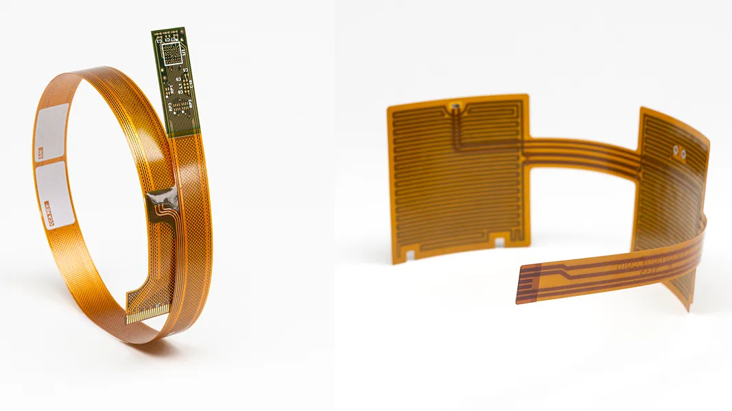
In the world of modern electronics, flexibility is key—literally. Flexible Printed Circuit Boards (Flex PCBs) are revolutionizing designs by allowing circuits to bend and fit into tight, complex spaces. But how do you ensure your Flex PCB bends without breaking? The secret lies in optimizing the bend radius during the Design for Manufacturing (DFM) process. In this blog, we’ll dive deep into flex PCB bend radius calculation, minimum bend radius for flex circuits, stress analysis in flex PCBs, dynamic bending applications, and material selection for flex PCBs. Whether you’re an engineer or a designer, this guide will help you create durable and efficient Flex PCB designs.
What Is Bend Radius in Flex PCBs and Why Does It Matter?
Bend radius refers to the minimum radius a Flex PCB can be bent without causing damage to the circuit or its components. Think of it as the tightest curve your board can handle before the materials start to crack, delaminate, or fail. Getting the bend radius right is critical in Flex PCB DFM because it directly impacts the reliability and longevity of your product. A poorly calculated bend radius can lead to mechanical stress, broken traces, or even complete circuit failure.
In short, optimizing the bend radius ensures your design can withstand the physical demands of its application—whether it’s a wearable device bending with movement or a compact gadget folding into a tight space. Let’s explore how to calculate and apply the right bend radius for your project.
How to Calculate Flex PCB Bend Radius
Calculating the flex PCB bend radius is a crucial step in the design process. The goal is to determine the smallest radius your board can handle without risking damage. While the exact calculation depends on factors like material thickness and layer count, a general rule of thumb can guide you.
For a single-layer Flex PCB, the minimum bend radius is often calculated as 6 times the thickness of the board. For multi-layer Flex PCBs, this increases to about 10-12 times the thickness due to the added complexity and stress on the layers. Here’s a simple formula to get started:
- Minimum Bend Radius = Thickness of Flex PCB × Multiplier (6 for single-layer, 10-12 for multi-layer)
For example, if your single-layer Flex PCB has a thickness of 0.1 mm, the minimum bend radius would be 0.6 mm. For a multi-layer board of the same thickness, it could be 1.0 to 1.2 mm. These values are starting points, and you’ll need to adjust based on the specific materials and application.
Beyond the formula, consider consulting industry standards like IPC-2223, which provides detailed guidelines on bend radius for different types of Flex PCBs. Testing prototypes under real-world conditions is also a smart way to validate your calculations.
Understanding the Minimum Bend Radius for Flex Circuits
The minimum bend radius for flex circuits is the smallest radius at which the board can bend without sustaining damage. Pushing beyond this limit risks cracking the copper traces, delaminating the layers, or causing other mechanical failures. Several factors influence this minimum value:
- Material Thickness: Thinner materials generally allow for tighter bends. For instance, a 0.05 mm thick polyimide film can achieve a smaller bend radius than a 0.2 mm thick one.
- Layer Count: More layers mean more internal stress during bending, requiring a larger minimum radius.
- Copper Weight: Heavier copper (e.g., 2 oz) is less flexible than lighter copper (e.g., 0.5 oz), increasing the minimum bend radius.
- Application Type: Static bends (bent once and fixed) can often tolerate tighter radii than dynamic bends (repeated bending), which we’ll discuss later.
As a practical example, a double-layer Flex PCB with 1 oz copper and a thickness of 0.15 mm might have a minimum bend radius of around 1.5 mm for static applications. Always refer to material datasheets and manufacturer recommendations to fine-tune these numbers for your design.
Stress Analysis in Flex PCBs: Preventing Failure
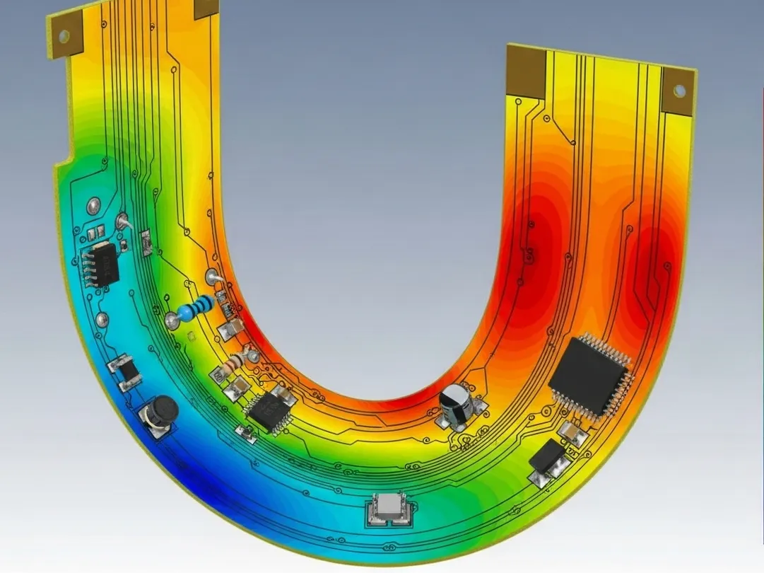
Bending a Flex PCB introduces mechanical stress, especially in the copper traces and dielectric layers. Conducting a stress analysis in flex PCBs helps identify potential weak points before they become problems. Stress is highest at the innermost part of the bend, where the material is compressed, and at the outermost part, where it is stretched.
To perform a basic stress analysis, engineers often use Finite Element Analysis (FEA) software to simulate bending conditions. This tool can predict how much stress a specific bend radius will place on the board and whether it exceeds the material’s limits. For instance, polyimide, a common Flex PCB material, has a tensile strength of about 231 MPa. If your simulation shows stress levels approaching this value, it’s a sign to increase the bend radius or choose a different material.
Another key factor in stress analysis is the placement of components and traces. Avoid placing rigid components or vias in the bend area, as they can create stress concentration points. Instead, route traces perpendicular to the bend to minimize strain. By understanding and mitigating stress, you can extend the lifespan of your Flex PCB.
Dynamic Bending Applications: Designing for Repeated Flexing
Not all Flex PCBs are bent once and left in place. In dynamic bending applications, the board undergoes repeated flexing, such as in wearable devices, hinges, or foldable electronics. These applications demand extra attention to bend radius and material durability.
For dynamic bending, the minimum bend radius often needs to be larger than for static applications—sometimes 20 times the thickness or more. This reduces stress and prevents fatigue over thousands or millions of bend cycles. For example, a Flex PCB in a smartwatch might endure 10,000 bends over its lifetime. If the bend radius is too tight, the copper traces could crack after just a few hundred cycles.
Testing is critical for dynamic applications. Use a bending test machine to simulate real-world conditions and ensure your design holds up. Also, consider adding reinforcements like stiffeners outside the bend area to distribute stress more evenly. By prioritizing durability in dynamic designs, you can avoid costly failures down the line.
Material Selection for Flex PCBs: Balancing Flexibility and Strength
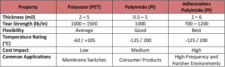
Choosing the right materials is at the heart of optimizing bend radius. The material selection for flex PCBs directly affects how much the board can bend and how well it withstands stress. Here are the key materials to consider:
- Base Material: Polyimide is the go-to choice for most Flex PCBs due to its excellent flexibility, thermal stability (up to 400°C), and tensile strength. It supports tight bend radii and is ideal for both static and dynamic applications.
- Copper Foil: Rolled annealed (RA) copper is preferred over electrodeposited (ED) copper because it’s more ductile and less prone to cracking during bending. RA copper can handle bend radii as tight as 0.5 mm in thin layers.
- Adhesives: Adhesive-less constructions are often better for tight bends since they reduce thickness and improve flexibility. If adhesives are needed, opt for flexible ones that won’t crack under stress.
- Coverlay: A polyimide coverlay protects the circuit while maintaining flexibility. Its thickness (typically 0.025 mm to 0.05 mm) should be factored into bend radius calculations.
When selecting materials, balance flexibility with other requirements like thermal performance and cost. Thinner materials allow for tighter bends but may sacrifice durability. Work closely with your manufacturing partner to choose materials that align with your design goals.
Best Practices for Flex PCB DFM to Optimize Bend Radius
Designing a Flex PCB that bends without breaking requires careful attention to DFM principles. Here are some actionable tips to optimize bend radius and ensure a reliable design:
- Avoid Sharp Bends: Gradual curves reduce stress compared to sharp angles. If a tight bend is unavoidable, consider a larger radius or additional layers for support.
- Route Traces Wisely: Run traces perpendicular to the bend line to minimize strain. Use curved traces instead of sharp corners to avoid stress points.
- Use Teardrop Pads: Adding teardrop-shaped pads at via connections strengthens the joint and reduces the risk of cracking during bending.
- Minimize Layer Count in Bend Areas: Reduce the number of layers in the bend zone to lower stress and achieve a smaller bend radius.
- Add Stiffeners: For dynamic applications, stiffeners can reinforce areas outside the bend zone, preventing unintended flexing.
By following these practices, you can create a Flex PCB design that’s both flexible and robust, ready to meet the demands of your application.
Common Mistakes to Avoid in Flex PCB Bend Radius Design
Even experienced designers can make mistakes when optimizing bend radius. Here are some common pitfalls to watch out for:
- Underestimating Bend Radius: Choosing a radius that’s too tight can lead to immediate or long-term failure, especially in dynamic applications.
- Ignoring Material Limits: Not all materials are equal. Using a less flexible material without adjusting the bend radius can cause cracks or delamination.
- Placing Components in Bend Zones: Rigid components in the bend area are prone to damage and can create stress points that lead to failure.
- Skipping Stress Analysis: Without proper analysis, you might miss hidden stress points that only reveal themselves after repeated use.
Avoiding these mistakes can save time, money, and frustration during the design and manufacturing process.
Conclusion: Mastering Bend Radius for Flex PCB Success
Optimizing bend radius in Flex PCB DFM is all about finding the sweet spot between flexibility and durability. By mastering flex PCB bend radius calculation, understanding the minimum bend radius for flex circuits, performing stress analysis in flex PCBs, designing for dynamic bending applications, and making informed decisions on material selection for flex PCBs, you can create designs that bend without breaking.
Remember to start with accurate calculations, choose materials that match your application’s needs, and follow DFM best practices to minimize stress and maximize reliability. With these strategies, your Flex PCB designs will not only meet performance expectations but also stand the test of time in even the most demanding environments.
Ready to bring your Flex PCB project to life? Partner with a trusted manufacturer to ensure your design is optimized from concept to production. Let’s build flexible, durable, and innovative solutions together.


