ALLPCB


In the world of printed circuit board (PCB) manufacturing, ensuring quality is non-negotiable. Automated Optical Inspection (AOI) plays a critical role in identifying defects early in the production process. But did you know that the effectiveness of AOI largely depends on proper lighting? In this comprehensive guide, we’ll dive into AOI lighting types, AOI lighting angles, and AOI lighting setup to help you achieve superior PCB inspection results. Whether you're a seasoned engineer or new to the field, this post will illuminate the best practices for optimizing your AOI system.
Let’s explore how the right lighting techniques can make all the difference in detecting even the smallest defects on complex PCBs, ensuring your products meet the highest standards of reliability and performance.
Why Lighting Matters in AOI for PCB Inspection
Lighting is the backbone of any AOI system. Without proper illumination, even the most advanced cameras and software can miss critical defects like misaligned components, soldering issues, or tiny cracks. AOI systems rely on high-resolution images to compare a PCB against a reference design, and poor lighting can result in shadows, glare, or insufficient contrast, leading to false positives or missed errors.
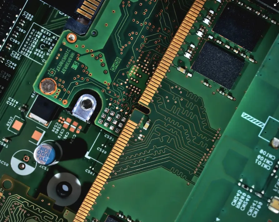
Modern PCBs are often densely populated with components of varying heights and materials, making uniform illumination a challenge. A well-designed lighting setup ensures that every part of the board—whether it’s a tall capacitor or a tiny surface-mount resistor—is clearly visible. By mastering AOI lighting techniques, manufacturers can reduce defect rates by up to 40% and improve inspection accuracy significantly, as noted in recent industry studies.
Understanding AOI Lighting Types for PCB Inspection
Choosing the right type of lighting is the first step in optimizing your AOI system. Different lighting types serve specific purposes, depending on the PCB design and the defects you’re targeting. Below are the most common AOI lighting types used in PCB inspection:
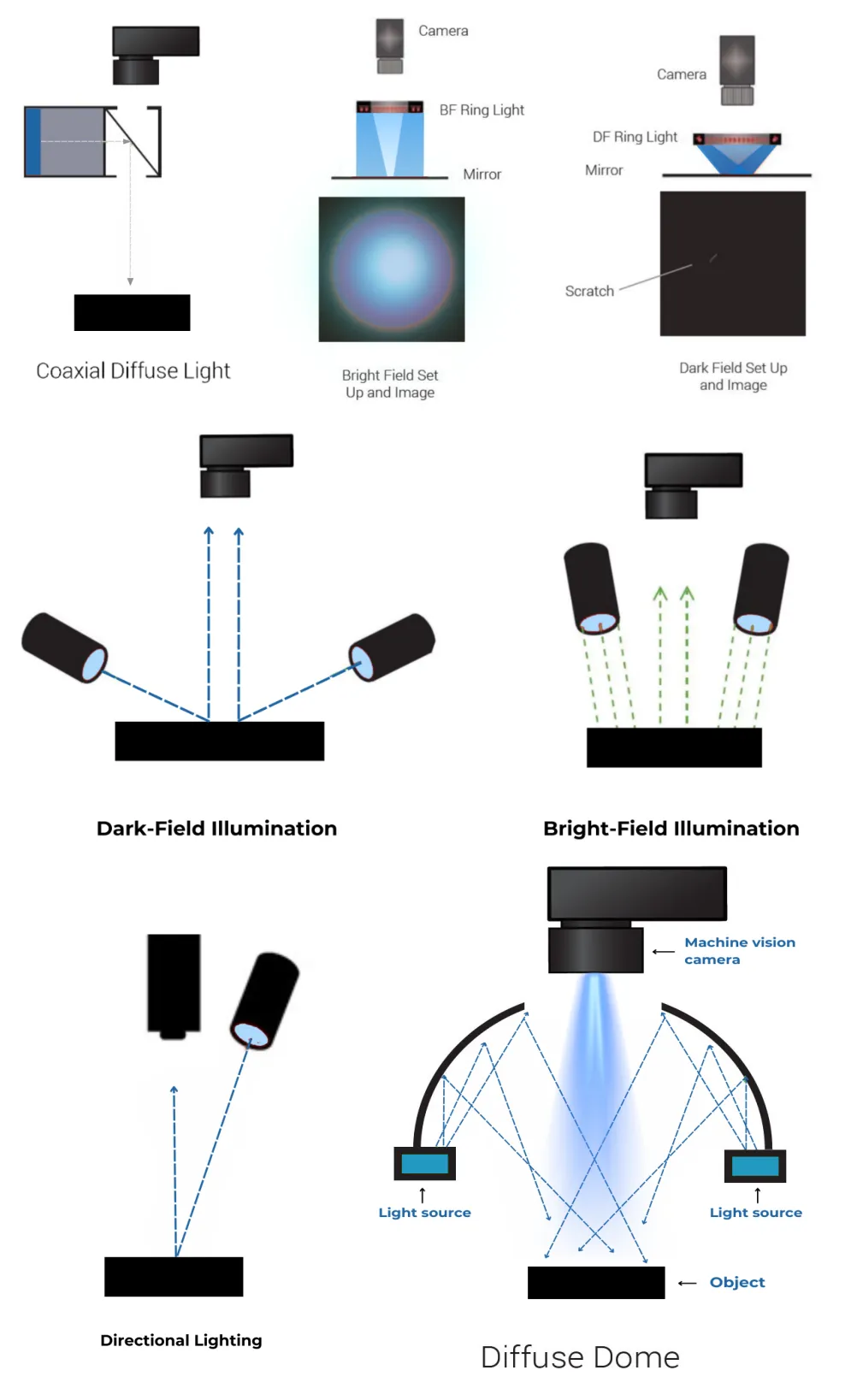
1. Coaxial Lighting
Coaxial lighting, also known as on-axis lighting, directs light straight down onto the PCB surface through a beam splitter. This type of lighting is ideal for inspecting flat, reflective surfaces as it minimizes shadows and glare. It’s particularly useful for detecting surface scratches or defects on polished components. However, it may struggle with taller components where side illumination is needed.
2. Ring Lighting
Ring lighting uses a circular array of light sources positioned around the camera lens. This setup provides uniform illumination from all directions, reducing shadows on uneven surfaces. It’s a go-to choice for general-purpose PCB inspection, especially for boards with mixed component heights. By adjusting the intensity, ring lighting can highlight defects like missing components or misaligned solder joints.
3. Dome Lighting
Dome lighting creates a diffused, shadow-free illumination by bouncing light off a dome-shaped reflector onto the PCB. This type is excellent for highly reflective or curved surfaces where glare could obscure defects. Dome lighting ensures consistent image quality, even on complex board layouts, making it easier to spot issues like solder bridging or insufficient solder.
4. Backlighting
Backlighting places the light source beneath the PCB, shining upward through transparent or semi-transparent areas. This technique is perfect for inspecting through-hole components or verifying hole alignment. It creates high contrast between the board material and open spaces, making defects like missing holes or misdrilled vias stand out clearly.
5. Programmable Multi-Color Lighting
Programmable lighting with multiple colors (often using LEDs) allows for dynamic adjustments during inspection. For instance, red light might enhance contrast on certain materials, while blue light could reveal defects on others. This flexibility is invaluable for inspecting PCBs with diverse finishes and components, ensuring maximum defect coverage across various conditions.
Optimizing AOI Lighting Angles for Maximum Clarity
Beyond choosing the right type of lighting, the angle at which light hits the PCB is just as crucial. The correct AOI lighting angles can highlight specific defects that might otherwise go unnoticed. Here’s how different angles impact inspection quality:
Low-Angle Lighting
Low-angle lighting, often set at 10 to 30 degrees from the PCB surface, emphasizes surface texture and height differences. It’s highly effective for detecting defects like lifted leads, tombstoning (where components stand upright due to uneven soldering), or uneven solder paste. By casting shadows on raised elements, low-angle lighting makes it easier to spot dimensional issues.
High-Angle Lighting
High-angle lighting, positioned at 60 to 90 degrees, provides broad, even illumination across the PCB. This angle is ideal for general inspection as it minimizes shadows and ensures that flat areas are well-lit. It’s often used with ring or coaxial lighting to capture clear images of the board’s overall layout and component placement.
Side-Angle Lighting
Side-angle lighting, set at 30 to 60 degrees, strikes a balance between low and high angles. It’s particularly useful for illuminating taller components without creating harsh shadows on shorter ones. This angle helps reveal defects on component sides, such as cracks or misalignments, and is often paired with programmable lighting for adjustable intensity.
Many advanced AOI systems combine multiple angles during a single inspection cycle. For example, a system might use low-angle lighting to check for solder joint issues and switch to high-angle lighting for overall component placement. Adjusting angles dynamically can improve defect detection rates by up to 30%, based on industry benchmarks.
Setting Up Your AOI Lighting for Optimal Results
A well-thought-out AOI lighting setup ties together the right lighting types and angles to create a robust inspection process. Here are the key steps to configure your AOI lighting system for superior PCB quality control:
Step 1: Assess Your PCB Design
Start by analyzing the specific characteristics of your PCB. Are there tall components that might cast shadows? Does the board have reflective surfaces that could cause glare? Understanding these factors will help you choose the appropriate lighting type and angle. For instance, a board with mixed component heights might benefit from a combination of ring lighting at a high angle and low-angle side lighting.
Step 2: Select the Right Lighting Hardware
Invest in high-quality lighting hardware that supports flexibility. Modern AOI systems often use LED arrays because they’re energy-efficient, long-lasting, and easily programmable for different colors and intensities. Ensure your setup can accommodate multiple lighting types, such as coaxial and dome, to handle a variety of inspection needs.
Step 3: Position Lights Strategically
Place lights at angles that complement your inspection goals. For example, position low-angle lights around the perimeter of the inspection area to highlight height-related defects. Use high-angle lights directly above the PCB for overall illumination. If possible, integrate adjustable mounts so you can fine-tune angles during testing.
Step 4: Calibrate Intensity and Color
Too much light can wash out details, while too little can obscure defects. Calibrate the intensity of your lights to achieve optimal contrast. If using multi-color lighting, test different wavelengths to see which ones best highlight specific defects. For instance, green light at 550 nm wavelength often provides good contrast for solder joint inspection on standard FR4 boards.
Step 5: Test and Refine
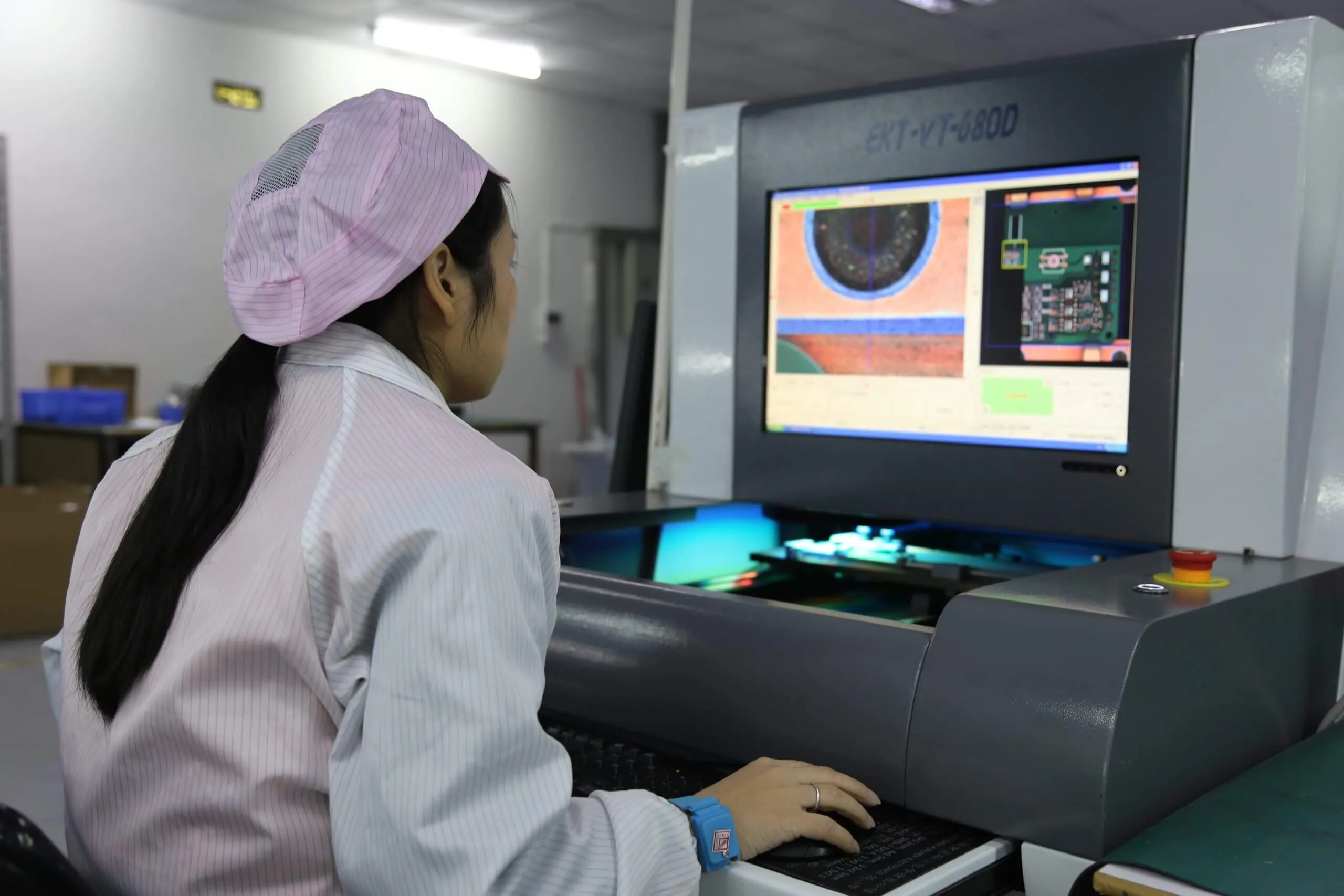
Run test inspections on sample PCBs to evaluate your lighting setup. Look for areas where defects are missed or false positives occur, and adjust the lighting accordingly. Modern AOI software often includes tools to analyze image quality, helping you pinpoint whether lighting adjustments are needed. Repeat this process until defect detection reaches an acceptable threshold, ideally above 95% accuracy.
Common Challenges in AOI Lighting and How to Overcome Them
Even with the best planning, AOI lighting setups can face challenges. Here are some common issues and practical solutions:
Shadows from Tall Components
Tall components like electrolytic capacitors can block light, hiding defects on nearby smaller components. Use a combination of side-angle and ring lighting to illuminate around obstacles. Adjusting the camera position slightly off-axis can also help capture hidden areas.
Glare on Reflective Surfaces
Highly reflective surfaces, such as gold-plated connectors, can cause glare that obscures details. Switch to diffused lighting, like dome lighting, to reduce reflections. Polarizing filters on the camera lens can further minimize glare without sacrificing image quality.
Inconsistent Lighting Across Large Boards
For larger PCBs, ensuring uniform lighting across the entire surface can be difficult. Use multiple light sources strategically placed around the inspection area, and consider programmable lighting arrays that can adjust intensity in specific zones. Regularly calibrate the system to maintain consistency.
Benefits of a Well-Designed AOI Lighting System
Investing time and resources into perfecting your AOI lighting setup pays off in numerous ways. A well-optimized system can detect over 95% of defects, including subtle issues like hairline cracks or micro-solder defects. It reduces the need for manual inspection, cutting labor costs by up to 20% in some manufacturing environments. Additionally, catching defects early prevents costly rework or product recalls, safeguarding your reputation for quality.
Beyond defect detection, proper lighting enhances the efficiency of your AOI system. High-quality images captured under optimal illumination allow inspection software to process data faster, sometimes achieving frame rates of up to 100 fps with modern high-resolution cameras. This speed translates to higher throughput, enabling you to meet tight production deadlines without compromising on quality.
Final Thoughts on AOI Lighting Techniques
Mastering AOI lighting types, AOI lighting angles, and AOI lighting setup is essential for achieving superior PCB inspection outcomes. By selecting the right lighting hardware, positioning lights at optimal angles, and fine-tuning intensity and color, you can ensure that every defect—no matter how small—is illuminated and identified. A thoughtful approach to AOI lighting not only boosts defect detection rates but also streamlines production, reduces costs, and upholds the highest standards of quality.
As PCB designs continue to grow in complexity with smaller components and denser layouts, the role of effective lighting in AOI will only become more critical. Stay ahead of the curve by regularly evaluating and updating your lighting techniques to match the evolving demands of electronics manufacturing. With the right illumination, your AOI system will shine as a cornerstone of reliable, high-quality PCB production.