ALLPCB


Designing a printed circuit board (PCB) for a vending machine can seem like a daunting task, especially if you're new to the field. But with the right approach, tools, and tips, you can create a reliable and efficient PCB that powers a vending machine's complex operations. Whether you're looking for a step-by-step vending machine PCB design process, layout tips, software recommendations, or guidance for beginners, this guide has you covered. We'll walk you through everything you need to know to take your vending machine PCB from concept to reality.
Why Vending Machine PCB Design Matters
Vending machines are intricate systems that rely on precise electronics to handle tasks like accepting payments, dispensing products, and displaying information. At the heart of these operations lies the PCB, which connects and controls components like motors, sensors, displays, and communication modules. A well-designed PCB ensures smooth functionality, minimizes errors, and reduces maintenance costs. Poor design, on the other hand, can lead to malfunctions, signal interference, or even safety hazards. This guide aims to help you avoid common pitfalls and build a robust PCB tailored for vending machines.

Understanding the Basics of Vending Machine PCB Design for Beginners
If you're just starting out, it's important to grasp the fundamental role of a PCB in a vending machine. The PCB acts as the central hub, managing inputs (like coin or card payments) and outputs (like product dispensing or screen updates). For beginners, the design process can be broken down into manageable steps. You'll need to define the machine's requirements, choose the right components, and create a layout that ensures everything works together seamlessly. Don't worry if this sounds complex— we'll break it down further in the following sections to make it approachable even for those with minimal experience.
Key Components of a Vending Machine PCB
Before diving into the design process, let's look at the typical components you'll find on a vending machine PCB:
- Microcontroller Unit (MCU): The brain of the system, controlling logic and decision-making. A common choice might support 32-bit processing with a clock speed of around 48-80 MHz to handle multiple tasks.
- Power Supply Circuit: Converts input voltage (often 12V or 24V) to stable levels for components, like 5V or 3.3V, with current ratings of 1-2A for most modules.
- Motor Drivers: Control the motors for dispensing products, often handling loads up to 1A per motor for 25-30 motors in larger machines.
- Sensors: Detect coins, bills, or product availability, requiring low-noise signal paths for accuracy.
- Communication Modules: Enable Wi-Fi or cellular connectivity for remote updates or cashless payments, often operating at 2.4 GHz for standard wireless protocols.
- Display Interface: Drives an LCD or LED screen to show menus or transaction details, typically requiring SPI or I2C communication at speeds up to 1 MHz.
Understanding these components and their electrical needs is the first step in creating a functional PCB design for a vending machine.
The Vending Machine PCB Design Process: Step by Step
Designing a PCB for a vending machine involves a structured approach. Below, we outline the complete vending machine PCB design process to help you move from an idea to a working board.
Step 1: Define Requirements and Specifications
Start by listing the functionalities your vending machine needs. Will it accept coins, bills, or card payments? How many products will it dispense, and what kind of motors are required? Define power needs (e.g., 24V input for heavy motors) and environmental factors (like temperature ranges of 0-50°C for outdoor machines). Create a block diagram to map out major components and their interactions. This step ensures you don’t miss critical features during design.
Step 2: Schematic Design
Once requirements are clear, create a schematic diagram. This is a blueprint showing how components connect electrically. Use design software to place your MCU, power supply, motor drivers, sensors, and other modules. Ensure proper voltage levels (e.g., 5V for sensors, 3.3V for communication chips) and include decoupling capacitors (typically 0.1μF near ICs) to stabilize power. Double-check connections to avoid short circuits or signal mismatches.

Step 3: Component Selection
Choose components based on your schematic and requirements. Opt for reliable, industry-standard parts with datasheets specifying parameters like voltage tolerance (±5%) and current limits (e.g., 500mA for small motors). For an MCU, ensure it has enough GPIO pins (at least 30 for a machine with 25 motors and additional sensors). Consider future scalability—select components with slightly higher specs to accommodate upgrades.
Step 4: PCB Layout Design
With the schematic ready, move to the PCB layout. This step involves placing components on a board and routing traces to connect them. Follow best practices like keeping power and ground planes separate to reduce noise, and place high-current components (like motor drivers) away from sensitive analog circuits (like sensors). Aim for trace widths of 10-20 mils for signal lines and 30-50 mils for power lines carrying 1-2A to prevent overheating.
Step 5: Design Rule Check (DRC) and Testing
Run a design rule check in your software to catch errors like overlapping traces or insufficient clearances (maintain at least 8 mils between traces for standard 1 oz copper boards). Generate a prototype and test it for functionality—verify motor control, payment detection, and display output. Use a multimeter to check voltages (e.g., 5V at sensor inputs) and an oscilloscope to monitor signal integrity (ensure noise is below 50mV peak-to-peak on critical lines).
Step 6: Finalize and Manufacture
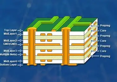
After testing, refine your design based on feedback. Generate Gerber files, which are the industry-standard format for PCB manufacturing, and submit them to a trusted fabrication service. Ensure your board house supports specifications like 2-layer or 4-layer boards with 1.6mm thickness for durability in vending machine applications.
Vending Machine PCB Layout Tips for Optimal Performance
The layout phase is critical in ensuring your PCB operates without issues. Here are some vending machine PCB layout tips to keep in mind, especially if you're new to this process.
1. Prioritize Component Placement
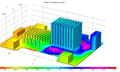
Place components logically—group related parts together. For example, keep the MCU near communication modules to shorten signal traces (ideally under 2 inches to minimize delay at 1 MHz speeds). Position high-heat components like voltage regulators near board edges for better cooling, and ensure motor drivers have access to thick power traces (at least 40 mils for 2A currents).
2. Minimize Signal Interference
Route sensitive analog signals (like sensor outputs) away from noisy digital lines (like motor control signals). Use ground planes to shield signals and reduce electromagnetic interference (EMI). Maintain a signal-to-noise ratio above 20 dB for reliable sensor readings by avoiding trace crossings over split planes.
3. Optimize Power Distribution
Design a solid power distribution network. Use wide traces or copper pours for power and ground to handle currents up to 5A for multiple motors. Add bypass capacitors (e.g., 10μF near power pins) to filter noise, ensuring voltage drops stay below 0.2V during peak loads.
4. Account for Mechanical Constraints
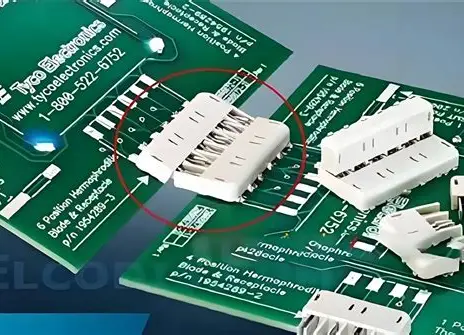
Vending machines have limited space, so design your PCB to fit within the enclosure. Use mounting holes (typically 3.2mm diameter) aligned with the machine’s frame. Keep connectors accessible for easy wiring to external components like coin acceptors or displays.

Best Vending Machine PCB Design Software for Beginners
Choosing the right tools can make or break your design experience. Here are some recommended options for vending machine PCB design software, focusing on user-friendly platforms that cater to beginners while offering powerful features.
1. Free and Open-Source Software
For those on a budget, free tools are a great starting point. These platforms offer schematic capture and layout features suitable for small to medium vending machine projects. They often include libraries with common components like MCUs and motor drivers, and support 2-layer boards with trace widths down to 6 mils for compact designs.
2. Professional-Grade Software with Free Trials
Some advanced tools offer free trials or educational versions. These are ideal for learning complex designs, supporting multi-layer boards (up to 16 layers) and high-speed routing with impedance control (e.g., 50 ohms for communication lines). They also include simulation features to test signal integrity before manufacturing.
3. Cloud-Based Design Platforms
Cloud-based tools allow collaboration and access from any device, which is perfect for teams working on vending machine projects. They often integrate schematic and layout design with real-time error checking, ensuring clearances meet standards (like 10 mils for 1 oz copper). Look for platforms with intuitive interfaces for beginners.
Regardless of the software, ensure it supports exporting Gerber files and offers a design rule check feature to catch errors early. Start with tutorials provided by the software to familiarize yourself with the interface before tackling a full vending machine PCB design.
Common Challenges in Vending Machine PCB Design and How to Overcome Them
Designing a PCB for a vending machine comes with unique challenges. Here are a few common issues and solutions to help you navigate them.
1. Handling High Current for Motors
Vending machines often use multiple motors, each drawing 0.5-1A. This can cause voltage drops or overheating. Solution: Use thick traces (50 mils or more) for power delivery and add heat sinks to motor drivers if dissipation exceeds 1W per component.
2. Managing EMI from Multiple Components
With motors, displays, and wireless modules on the same board, EMI can disrupt signals. Solution: Use separate ground planes for analog and digital sections, and add ferrite beads to filter high-frequency noise on power lines (rated for 1A at 100 MHz).
3. Fitting Complex Designs in Limited Space
Space constraints can make layout tricky. Solution: Opt for surface-mount components (SMD) over through-hole to save space, and consider a 4-layer board to stack power and signal layers, reducing footprint while maintaining 10-mil clearances.
Final Thoughts on Vending Machine PCB Design
Creating a PCB for a vending machine is a rewarding challenge that combines creativity with technical precision. By following a structured vending machine PCB design process, applying practical layout tips, and using beginner-friendly design software, you can bring your concept to life. Remember to start with clear requirements, prioritize component placement and signal integrity, and test thoroughly before manufacturing. With these steps, you'll be well on your way to designing a reliable PCB that powers a successful vending machine.
At ALLPCB, we’re committed to supporting engineers and designers at every stage of their projects. Whether you're a beginner or a seasoned professional, our resources and manufacturing services are here to help turn your vending machine PCB designs into reality with precision and efficiency.