ALLPCB


Designing a power distribution network (PDN) for retail display PCBs is critical to ensuring reliable performance, minimizing voltage drops, and maintaining power integrity. Whether you're powering LED screens, interactive kiosks, or digital signage, a well-designed PDN can make the difference between a seamless user experience and costly downtime. In this comprehensive guide, we'll explore the essentials of retail display PCB power distribution, dive into PCB voltage drop calculation, and discuss power plane design for retail displays to help you create efficient and robust systems.
Why Power Distribution Matters for Retail Display PCBs
Retail displays, such as digital signage and point-of-sale systems, rely heavily on printed circuit boards (PCBs) to function. These systems often operate for long hours under varying conditions, making stable power delivery a top priority. A poorly designed PDN can lead to issues like voltage drops, overheating, and signal interference, which can disrupt the display's performance and frustrate customers.
A strong PDN ensures that every component on the PCB receives the correct voltage and current, even during peak demand. For retail displays, where aesthetics and reliability are key, optimizing the power distribution network is not just a technical requirement—it's a business necessity.

Key Components of a Power Distribution Network in Retail Display PCBs
Before diving into the design process, let's break down the main elements of a PDN for retail display PCBs. Understanding these components will help you build a system that delivers consistent power and minimizes disruptions.
- Power Planes: These are dedicated copper layers in the PCB that distribute voltage across the board. Using separate planes for different voltage levels (e.g., 3.3V for logic circuits and 12V for LED drivers) helps reduce noise and interference.
- Decoupling Capacitors: Placed near power-hungry components, these capacitors smooth out voltage fluctuations and provide a quick source of current during sudden demand spikes.
- Vias and Traces: These connect the power planes to components. Properly sized traces and strategically placed vias minimize resistance and ensure even power distribution.
- Ground Planes: A solid ground plane reduces electromagnetic interference (EMI) and provides a return path for current, which is crucial for maintaining signal integrity in retail displays.
Steps to Design an Effective Power Distribution Network for Retail Displays
Creating a reliable PDN for retail display PCBs requires careful planning and attention to detail. Below are the key steps to follow during the design process.
1. Define Power Requirements
Start by identifying the power needs of each component on your retail display PCB. For example, LED drivers might require 12V at 2A, while microcontrollers may need 3.3V at 500mA. List all voltage levels and current demands to ensure your PDN can handle the load. Overlooking even a single component can lead to voltage drops or system failures.
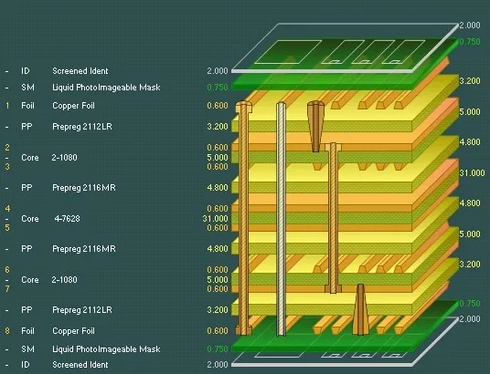
2. Choose the Right Layer Stack-Up
For retail display PCBs, a multi-layer design is often necessary to accommodate power and ground planes. A common stack-up might include:
- Top Layer: Signal traces and components
- Layer 2: Ground plane
- Layer 3: Power plane (e.g., 3.3V)
- Layer 4: Power plane (e.g., 12V)
- Bottom Layer: Additional signals or ground
This structure minimizes interference and ensures dedicated space for power distribution. For high-current applications, consider using thicker copper (e.g., 2 oz/ft2) to reduce resistance.
3. Place Decoupling Capacitors Strategically
Position decoupling capacitors as close as possible to the power pins of integrated circuits (ICs) and other high-demand components. For instance, a 0.1μF ceramic capacitor can handle high-frequency noise, while a 10μF capacitor can address lower-frequency fluctuations. This placement reduces the loop inductance and ensures stable voltage delivery.
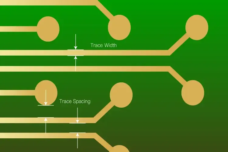
4. Minimize Voltage Drops with Proper Trace and Via Design
Voltage drop occurs when resistance in traces or vias causes a reduction in voltage as current flows through them. To minimize this, use wider traces for high-current paths and avoid long, narrow traces. For example, a trace carrying 2A should be at least 50 mils wide for a 1 oz/ft2 copper layer to keep the voltage drop below 0.1V over a 2-inch length.
Additionally, use multiple vias when transitioning between layers to reduce resistance. A single via might have a resistance of 1-2 mΩ, but using four vias in parallel can cut this down significantly.
PCB Voltage Drop Calculation: A Step-by-Step Guide
Voltage drop is a critical factor in retail display PCB power distribution. Excessive drops can lead to underpowered components, causing flickering displays or system crashes. Calculating voltage drop helps you design traces and planes that maintain stable power delivery. Here's how to do it:
Step 1: Determine Current and Trace Length
Identify the current (I) flowing through a trace and the length (L) of the trace. For example, if an LED driver draws 1.5A and the trace is 3 inches long, these are your starting values.
Step 2: Find Trace Resistance
Resistance (R) depends on the trace width, thickness, and material. For a 1 oz/ft2 copper trace that is 20 mils wide, the resistance is approximately 0.5 mΩ per inch. So, for a 3-inch trace, R = 0.5 mΩ/inch × 3 inches = 1.5 mΩ.
Step 3: Calculate Voltage Drop
Use Ohm's Law (V = I × R) to calculate the voltage drop. With I = 1.5A and R = 1.5 mΩ, the voltage drop V = 1.5A × 0.0015Ω = 0.00225V or 2.25mV. This small drop is acceptable for most applications, but for longer traces or higher currents, the drop could become significant.
Step 4: Adjust Design if Necessary
If the calculated voltage drop exceeds your tolerance (e.g., 1% of the supply voltage), widen the trace or use a thicker copper layer. For a 12V supply, a 1% tolerance means a maximum drop of 0.12V. Adjust your design to stay within this limit.
Power Plane Design for Retail Displays: Best Practices
Power plane design is a cornerstone of effective PDN for retail display PCBs. A well-designed power plane ensures uniform voltage distribution and reduces noise. Here are some best practices to follow:
1. Use Dedicated Power Planes for Each Voltage Level
For retail displays with multiple voltage requirements (e.g., 5V for sensors and 12V for backlighting), assign a separate power plane to each voltage. This prevents cross-talk and simplifies routing. If board space is limited, split a single plane into isolated regions, but ensure adequate spacing (e.g., 20 mils) to avoid coupling.
2. Keep Power and Ground Planes Close Together
Position power and ground planes on adjacent layers to minimize loop inductance. A separation of 4-10 mils between planes, achieved with a thin dielectric material, can reduce EMI and improve decoupling capacitor performance.
3. Avoid Cuts and Slots in Power Planes
Cuts or slots in power planes can disrupt current flow and create high-impedance paths, leading to voltage drops. If cuts are unavoidable due to component placement, ensure they are minimal and use stitching capacitors or vias to maintain continuity.
4. Simulate Power Plane Performance
Use simulation tools to analyze your power plane design before fabrication. These tools can predict voltage drops, current density, and thermal hotspots. For instance, a simulation might reveal that a certain area of the plane has a current density exceeding 50A/in2, indicating a need for thicker copper or additional vias.
Common Challenges in Retail Display PCB Power Distribution
Designing a PDN for retail displays comes with unique challenges. Below are some common issues and how to address them.
High Current Demands
Retail displays often include power-hungry components like LED arrays, which can draw several amps. To handle this, use thicker copper layers (e.g., 2 oz/ft2 or higher) and design wide traces or bus bars for high-current paths.
Thermal Management
High currents generate heat, which can affect display performance. Incorporate thermal vias and heat sinks near high-power components, and ensure power planes are not overloaded in specific areas.
Space Constraints
Retail display PCBs are often compact, leaving little room for wide traces or multiple planes. In such cases, prioritize critical power paths and use high-density interconnect (HDI) techniques to fit more layers into a smaller space.
Benefits of a Well-Designed Power Distribution Network
Investing time and effort into PDN design for retail display PCBs offers several advantages:
- Reliability: Stable power delivery prevents unexpected failures, ensuring continuous operation in high-traffic retail environments.
- Efficiency: Minimizing voltage drops and power losses reduces energy waste, lowering operating costs.
- Longevity: Proper thermal management and current distribution extend the lifespan of components, reducing maintenance needs.
Tips for Optimizing Retail Display PCB Power Distribution
To wrap up, here are some practical tips to enhance your PDN design:
- Always start with a detailed power budget to avoid underestimating current needs.
- Use PCB design software with built-in PDN analysis tools to identify potential issues early.
- Test prototypes under real-world conditions to validate your design before mass production.
- Consider future scalability—design with some headroom for additional components or higher power demands.
Conclusion
Designing a power distribution network for retail display PCBs is a complex but essential task. By focusing on retail display PCB power distribution, mastering PCB voltage drop calculation, and implementing effective power plane design for retail displays, you can create systems that deliver consistent performance and reliability. A well-thought-out PDN not only ensures smooth operation but also enhances the user experience in retail environments.
With the steps, calculations, and best practices outlined in this guide, you're equipped to tackle the challenges of PDN design. Take the time to plan, simulate, and test your designs, and you'll build retail display PCBs that stand up to the demands of modern retail technology.