 ALLPCB


Are you struggling to choose the right high-frequency inductor for your RF circuits? Understanding high frequency inductor selection, RF inductor characteristics, and how to pick the best inductor for RF circuits can make all the difference in achieving optimal performance. In this comprehensive guide, we’ll walk you through everything you need to know about high-frequency inductors, from their key features to practical tips for selection in RF applications. Whether you’re designing a wireless communication system or a high-speed signal filter, this blog will equip you with actionable insights to ensure your project succeeds.
What Are High-Frequency Inductors and Why Do They Matter in RF Applications?
High-frequency inductors are specialized components designed to operate effectively in radio frequency (RF) circuits, typically in the range of 100 kHz to several GHz. Unlike standard inductors used in power supplies, these components are optimized for minimal parasitic effects and high-quality performance at elevated frequencies. They play a crucial role in applications like impedance matching, signal filtering, and tuning circuits in devices such as smartphones, antennas, and radar systems.
The importance of selecting the right inductor for RF circuits cannot be overstated. A poorly chosen inductor can introduce signal loss, distortion, or unwanted resonance, leading to degraded performance. By understanding the unique characteristics of RF inductors, you can ensure your design operates efficiently and meets the demands of modern high-frequency systems.
Key RF Inductor Characteristics to Understand
Before diving into the selection process, it’s essential to grasp the critical characteristics that define an inductor’s performance in RF applications. These properties will directly impact how well the component functions in your circuit.
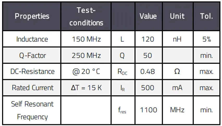
1. Inductance Value
The inductance value, measured in henries (H), or more commonly in microhenries (μH) or nanohenries (nH) for RF inductors, determines the component’s ability to store energy in a magnetic field. For high-frequency applications, inductance values typically range from 1 nH to 100 nH. Choosing the correct value ensures proper impedance matching or filtering at the desired frequency.
2. Quality Factor (Q)
The quality factor, or Q factor, measures the efficiency of an inductor by comparing its inductive reactance to its resistance. A higher Q value indicates lower energy loss and better performance, which is critical in RF circuits. For example, a Q factor above 30 is often desirable for applications operating at 1 GHz to minimize signal attenuation.
3. Self-Resonant Frequency (SRF)
The self-resonant frequency is the point at which an inductor’s parasitic capacitance causes it to behave like a capacitor rather than an inductor. For RF designs, you’ll want an inductor with an SRF much higher than your operating frequency. If your circuit operates at 2.4 GHz, select an inductor with an SRF of at least 3 GHz to avoid performance issues.
Related Reading: Component Selection for Impedance Matching Networks: Inductors vs. Capacitors in RF Circuits
4. DC Resistance (DCR)
DC resistance refers to the inherent resistance of the inductor’s wire or conductive material, measured in ohms (Ω). A lower DCR is preferred in RF applications to reduce power loss. Typical DCR values for high-frequency inductors range from 0.1 Ω to 1 Ω, depending on the size and construction.
5. Rated Current
The rated current specifies the maximum current the inductor can handle without overheating or saturating. In RF circuits, where currents are often low, rated current values between 100 mA and 500 mA are common. However, always check the specifications to ensure the inductor can handle your circuit’s requirements.
Factors to Consider for High Frequency Inductor Selection
Selecting the right inductor for RF circuits involves evaluating multiple factors to match the component with your specific application. Below are the key considerations to guide your decision-making process.
1. Operating Frequency Range
Your circuit’s operating frequency is the starting point for inductor selection. High-frequency inductors are designed for specific ranges, and using one outside its optimal range can lead to signal loss or resonance issues. For instance, a 5G application operating at 3.5 GHz requires an inductor specifically rated for that frequency band with a high SRF to avoid interference.
2. Application Type
Different RF applications demand different inductor properties. For impedance matching in an antenna circuit, you might prioritize a high Q factor. In contrast, a bandpass filter may require a specific inductance value to achieve the desired frequency response. Identify the primary function of the inductor in your design before narrowing down options.
3. Physical Size and Form Factor
RF inductors come in various package sizes, often in surface-mount technology (SMT) formats like 0402 or 0603 (imperial codes for dimensions in hundredths of an inch). Smaller sizes are ideal for compact designs in mobile devices, but they may have lower current ratings or Q factors. Balance the size constraints of your PCB layout with performance needs.
4. Material and Construction
The core material and construction of an inductor significantly affect its high-frequency performance. Ceramic core inductors are popular for RF applications due to their low loss and high Q factor at frequencies above 100 MHz. Wirewound inductors, on the other hand, may offer higher inductance but can introduce more parasitic effects at high frequencies.
5. Parasitic Effects
At high frequencies, parasitic capacitance and resistance can degrade inductor performance. Look for components with low parasitic values, as these unwanted effects can alter the behavior of your circuit. Datasheets often provide details on parasitic capacitance, typically in the range of 0.1 pF to 1 pF for RF inductors.
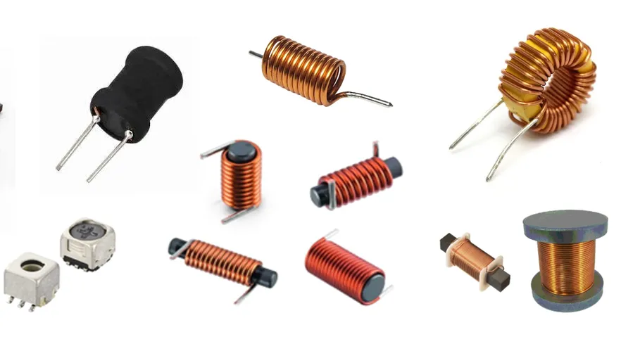
Common Types of High-Frequency Inductors for RF Circuits
Understanding the different types of inductors available for RF applications can help you make an informed choice. Here are the most common options:
1. Ceramic Chip Inductors
These are compact, surface-mount components with excellent high-frequency performance. They offer high Q factors and low parasitic capacitance, making them ideal for applications like wireless communication and GPS systems. Inductance values typically range from 1 nH to 100 nH.
2. Wirewound Inductors
Wirewound inductors are constructed by winding a wire around a core material. While they can provide higher inductance values, their performance at frequencies above 1 GHz may be limited due to higher parasitic effects. They are often used in lower-frequency RF applications or where space is less constrained.
3. Thin-Film Inductors
Thin-film inductors are manufactured using advanced deposition techniques, resulting in precise inductance values and very high Q factors. They are suitable for ultra-high-frequency applications, such as 5G and radar systems, but may come at a higher cost.
4. Air-Core Inductors
Air-core inductors lack a magnetic core, reducing losses and parasitic effects at very high frequencies. They are often custom-designed for specific RF circuits but are less common in mass-produced SMT formats due to their larger size.
Practical Tips for Using High-Frequency Inductors in RF Designs
Beyond selection, proper implementation of inductors in your RF circuit design is just as important. Here are some practical tips to maximize performance:
1. Minimize PCB Trace Lengths
Long PCB traces near inductors can introduce unwanted inductance or capacitance, affecting high-frequency signals. Keep traces as short as possible, especially in circuits operating above 1 GHz, to reduce parasitic effects.
2. Use Proper Grounding Techniques
Effective grounding is critical in RF designs to prevent noise and interference. Place ground vias close to the inductor’s ground pad to create a low-impedance path and reduce signal distortion.
3. Verify Inductor Placement
Position inductors away from noisy components like switching regulators or digital circuits. This helps avoid electromagnetic interference (EMI) that could degrade the inductor’s performance in sensitive RF applications.
4. Test Under Real-World Conditions
Simulations are valuable, but real-world testing is essential. Use a network analyzer to measure the inductor’s performance at your operating frequency, checking for unexpected resonance or signal loss. Adjust your design if the measured Q factor or SRF deviates from the datasheet values.
Challenges in High Frequency Inductor Selection and How to Overcome Them
Selecting and using high-frequency inductors for RF circuits can come with challenges. Here’s how to address some common issues:
1. Balancing Cost and Performance
High-performance inductors, such as thin-film types, can be expensive. If budget is a concern, consider ceramic chip inductors as a cost-effective alternative that still offers good Q factors and SRF for most RF applications below 3 GHz.
2. Dealing with Limited Space
In compact designs, fitting an inductor with the required specs can be tricky. Opt for smaller package sizes like 0201 or 0402, and prioritize inductors with high performance in a small footprint, even if it means a slight trade-off in current rating.
Related Reading: PCB Design Software for RF Applications: What Features are Essential?
3. Managing Temperature Effects
Temperature variations can alter an inductor’s performance, especially in outdoor or automotive RF applications. Choose inductors with stable characteristics over a wide temperature range, typically specified as -40°C to 85°C in datasheets.
How to Source High-Quality Inductors for Your RF Projects
Finding reliable high-frequency inductors is crucial for ensuring the success of your RF designs. Start by reviewing datasheets for detailed specifications on inductance, Q factor, SRF, and DCR. Partner with trusted suppliers who provide consistent quality and technical support. Additionally, consider prototyping with a small batch of inductors to test their performance in your specific application before full-scale production.
At ALLPCB, we understand the importance of quality components in your designs. Our platform offers resources and services to help you source the right parts and integrate them into your PCB layouts seamlessly, ensuring your RF projects meet the highest standards.
Conclusion: Mastering High-Frequency Inductors for RF Success
High-frequency inductors are vital components in RF applications, and making the right choice can significantly impact your circuit’s performance. By focusing on key RF inductor characteristics like Q factor, SRF, and DCR, and following a structured approach to high frequency inductor selection, you can ensure your design operates efficiently. Whether you’re working on a wireless communication system or a high-speed data link, the right inductor for RF circuits will help you achieve reliable and high-quality results.
This guide has covered everything from the basics of RF inductors to practical tips for implementation. Use this knowledge to refine your designs and overcome common challenges in high-frequency applications. With careful selection and proper design practices, your RF projects will reach new levels of performance.


